Valve closing device and valve closing method

A technology for closing devices and valves, which is applied in the direction of valve devices, valve operation/release devices, devices to prevent accidental or unauthorized actions, etc. It can solve the problems of affecting the sealing effect, wear of valve-related parts, and easy vibration.

Inactive Publication Date: 2021-01-22
刘径池
View PDF1 Cites 0 Cited by
  • Summary
  • Abstract
  • Description
  • Claims
  • Application Information

AI Technical Summary

Problems solved by technology

The above-mentioned patents have the following disadvantages: the fluid medium is used as the driving force for valve closure, but the locking components required to close the valve are lacking, so that after th

Method used


Image

  • Valve closing device and valve closing method
  • Valve closing device and valve closing method
  • Valve closing device and valve closing method

Examples


Embodiment 1

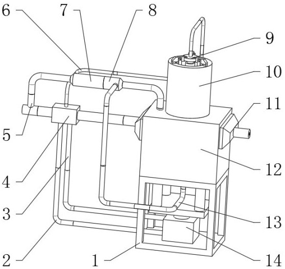
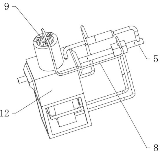
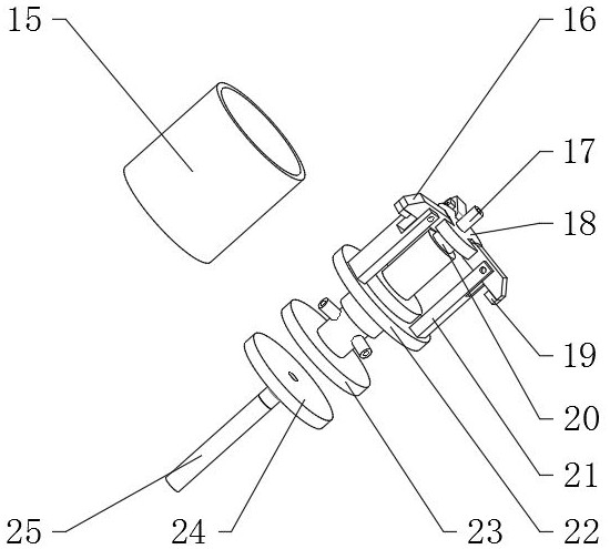
[0042] A valve closing device such as Figure 1-8 As shown, it includes the bottom frame 1, the top of the bottom frame 1 is fixedly connected with the action assembly 14, the top of the bottom frame 1 is fixedly connected with the shell 12, the top of the shell 12 is fixedly connected with the external cylinder 10, and the inner wall of the external cylinder 10 is fixed and slidingly connected. There is a locking assembly 9, a protruding tube 32 is fixedly connected to the top of the housing 12, and one end of the protruding tube 32 is fixedly connected to a rear compartment 8, and the inner wall of the rear compartment 8 is fixedly connected to a valve component 27; the locking component 9 includes The middle cylinder 15 and the tray 22, the bottom of the tray 22 is fixedly connected to the top of the middle cylinder 15, the top of the tray 22 is fixedly connected with a stand 21, the inner wall of the top of the stand 21 is connected with a pinch plate 16 through the shaft r...

Embodiment 2

[0046] A valve closing method of a valve closing device, such as Figure 1-7 shown, including the following steps:

[0047] S1: Preparation work; fixing device, connecting internal and external piping systems;

[0048] S2: The drive command is issued; the master control box 4 controls the corresponding state of the valve, and accepts external commands at the same time. When the valve needs to be closed, the master control box 4 starts;

[0049] S3: Close the shell 12; the electromagnetic commutator pours the fluid medium into the telescopic cylinder 31, and the telescopic cylinder 31 stretches out, pushing the valve core block 36 up, and the valve core block 36 closes the shell 12;

[0050] S4: Locking action; the head 34 is linked with the bending rod 35, the push head 33 stretches out to push the valve assembly 27, the fluid medium enters the rear compartment 8 through the push head 33, and then flows into the hose 2 13, followed by the lock assembly 9 start up;

[0051] ...


PUM


Abstract

The invention discloses a valve closing device and a valve closing method, and relates to the technical field of valves. The valve closing device and the valve closing method aim to solve the problemthat an existing closing device cannot achieve locking. The device comprises a bottom frame, an action assembly is fixedly connected to the top of the bottom frame, a shell is fixedly connected to thetop of the bottom frame, an external barrel is fixedly connected to the top of the shell, a locking assembly is fixedly and slidably connected to the inner wall of the external barrel, an extending pipe is fixedly connected to the top of the shell, a rear bin is fixedly connected to one end of the extending pipe, and a valve assembly is fixedly connected to the rear bin. The application method ofthe device comprises the following steps of preparation work, issuing of a driving instruction, closing of the shell, locking action, locking completion and valve closing. By arranging the locking assembly, a piston disc is pushed to move upwards, a buckle plate rotates and is pressed downwards immediately, a friction block makes contact with the top of the external barrel and is pressed tightly,and the locking function in the valve closed state is achieved.

Description

technical field [0001] The invention relates to the technical field of valves, in particular to a valve closing device and a valve closing method. Background technique [0002] The closing effect of the gate valve determines the use quality of the gate valve. In the closed state, the valve body needs to be locked to be effectively closed, and for the material of the fluid flowing through the valve, its locked state must be able to resist the vibration caused by the impact of fluid flow, and Existing valves are difficult to meet this function. [0003] After searching, the Chinese patent application number is 201710454063.8, which discloses a valve closing device and a valve closing method. The valve closing device comprises a housing, a first air inlet penetrating through the bottom of the housing, a resisting portion provided on the inner peripheral surface of the housing, a second air inlet passing through the side wall of the housing and located above the resisting porti...

Claims


Application Information

Patent Timeline
IPC IPC(8): F16K35/16F16K35/10F16K3/02F16K3/30F16K3/314F16K27/04F16K31/122
CPCF16K3/02F16K3/30F16K3/314F16K27/044F16K31/1223F16K35/10F16K35/16
Inventor 刘径池
Owner 刘径池
Why Eureka
Try Eureka