High-precision real-time attitude measurement device and method based on antenna turret

A high-precision, turret technology, used in measurement devices, navigation through velocity/acceleration measurement, mapping and navigation, etc., can solve the problems of inappropriate antenna turret attitude measurement, large influence, large volume and weight, etc. Achieve the effect of improving orientation and attitude measurement accuracy, reducing rowing error, and reducing volume and weight

Active Publication Date: 2021-01-22
BEIJING INST OF SPACE LAUNCH TECH
View PDF11 Cites 1 Cited by
  • Summary
  • Abstract
  • Description
  • Claims
  • Application Information

AI Technical Summary

Problems solved by technology

[0003] In the traditional strapdown inertial group, the IMU is directly connected to the carrier, and the alignment accuracy is greatly affected by the zero offset of the inertial device. Most of the existing strapdown inertial groups install the IMU on the built-in indexing mechanism. The alignment technology can be divided into coarse alignment In the two stages of alignment and fine alignment, the influence of the zero bias of the inertial device is offset by the rotation modulation method of multi-position rotation and stop, and high-precision azimuth and attitude information are obtained. However, this structure has a large volume and weight and is not suitable for antenna rotation. Tower attitude measurement

Method used


Image

  • High-precision real-time attitude measurement device and method based on antenna turret
  • High-precision real-time attitude measurement device and method based on antenna turret
  • High-precision real-time attitude measurement device and method based on antenna turret

Examples


Embodiment

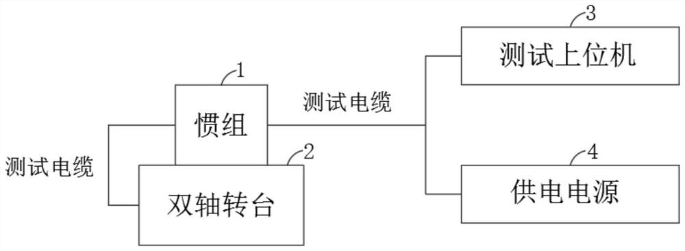
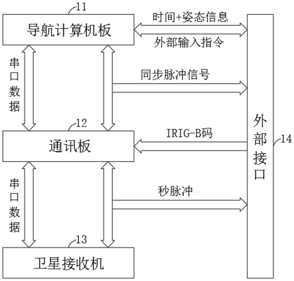
[0028] The present invention utilizes the double-axis turntable 2 equivalent antenna turret to provide the transposition function. The position accuracy of the double-axis turntable 2 is 2″, and the inertial group 1 is installed on the double-axis turntable. For specific hardware connections, please refer to figure 1 and figure 2 , its specific hardware includes:

[0029] Navigation computer board 11;

[0030] Communication board 12, described communication board 12 is bidirectionally connected with navigation computer board 11 by serial port data, and is connected with navigation computer board 11 unidirectionally by synchronous pulse signal;

[0031] Satellite receiver 13, said satellite receiver 13 is bidirectionally connected with communication board 12 through serial port data, and is unidirectionally connected with communication board 12 through second pulse signal;

[0032] External interface 14, the navigation computer board 11 is bidirectionally connected to the ex...


PUM


Abstract

The invention discloses a high-precision real-time attitude measurement device and method based on an antenna turret, and belongs to the technical field of real-time directional attitude measurement.The high-precision real-time attitude measurement device and method an inertial measurement unit, a double-shaft turntable and a test upper computer, wherein the double-shaft turntable simulates the use environment of the antenna turret, is electrically connected with the inertial measurement unit and drives the inertial measurement unit to rotate; and the test upper computer is electrically connected with the inertial measurement unit and is used for sending a control instruction and carrying out data acquisition and data processing at the same time. In order to meet the requirements of smallsize and real-time performance of attitude measurement at the same time, a pure strapdown inertial measurement unit without a built-in transposition mechanism is adopted, the size and weight of equipment can be effectively reduced by canceling the built-in transposition mechanism, and meanwhile, a flexible link of the transposition mechanism between an IMU and a base is removed, so that the real-time performance of attitude measurement of the inertial measurement unit can be improved; and in order not to reduce the alignment precision of the inertial measurement unit, the antenna turret is utilized to perform rotation modulation of two-position rotation and stop, so that a high-precision directional attitude measurement function is realized.

Description

technical field [0001] The invention relates to the technical field of real-time directional attitude measurement, and more specifically, to a high-precision real-time attitude measurement device and method based on an antenna turret. Background technique [0002] Strapdown inertial measurement unit (hereinafter referred to as "inertial unit") is widely used in azimuth and attitude measurement equipment on rockets, missiles, aircraft, etc. In order to improve the accuracy of orientation and attitude measurement, three high-precision laser gyroscopes and quartz The flexible accelerometer constitutes an inertial measurement unit (hereinafter referred to as "IMU"), which performs comprehensive calculations based on the angular velocity component of the earth's rotation sensed by the gyroscope and the gravity component sensed by the accelerometer to obtain the north azimuth and attitude angle. [0003] In the traditional strapdown inertial group, the IMU is directly connected to...

Claims


Application Information

Patent Timeline
Patent Type & Authority Applications(China)
IPC IPC(8): G01C21/16
CPCG01C21/165
Inventor 王瑾刘冰王盛白焕旭王庆广段祉鸿高艳李旬焦晨阳高秋娟陈雨
Owner BEIJING INST OF SPACE LAUNCH TECH
Why Eureka
Try Eureka