Vacuum pipeline speed measuring and positioning system and method

A technology of vacuum pipeline and positioning system, which is applied to devices using optical methods, image data processing, instruments, etc., can solve the problems of speed measurement failure, high cost, complicated construction, etc., and achieve the effect of high real-time accuracy and low cost

Pending Publication Date: 2022-02-18
HIWING TECH ACAD OF CASIC
View PDF0 Cites 0 Cited by
  • Summary
  • Abstract
  • Description
  • Claims
  • Application Information

AI Technical Summary

Problems solved by technology

[0004] For ground laser speed measurement and positioning, a laser sensor needs to be placed at a certain distance, and the speed measurement and positioning can be realized by blocking the laser sensor counting through the vehicle grating. The disadvantage is that the cost is high, and there is no speed monitoring on the vehicle; The disadvantage is that affected by the reflective surface or the speed exceeds a certain speed, the vehicle-mounted laser sensor may not be able to accurately receive the reflected beam, resulting in speed measurement failure, loss of points

Method used


Image

  • Vacuum pipeline speed measuring and positioning system and method
  • Vacuum pipeline speed measuring and positioning system and method
  • Vacuum pipeline speed measuring and positioning system and method

Examples


Embodiment Construction

[0049] It should be noted that, in the case of no conflict, the embodiments in the present application and the features in the embodiments can be combined with each other. The following will clearly and completely describe the technical solutions in the embodiments of the present invention with reference to the accompanying drawings in the embodiments of the present invention. Obviously, the described embodiments are only some, not all, embodiments of the present invention. The following description of at least one exemplary embodiment is merely illustrative in nature and in no way taken as limiting the invention, its application or uses. Based on the embodiments of the present invention, all other embodiments obtained by persons of ordinary skill in the art without creative efforts fall within the protection scope of the present invention.

[0050] It should be noted that the terminology used here is only for describing specific implementations, and is not intended to limit t...


PUM


Abstract

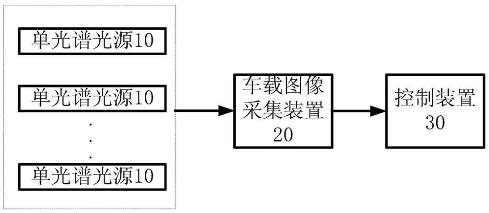
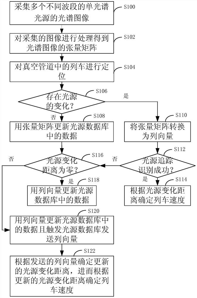
The invention discloses a vacuum pipeline speed measuring and positioning system and method. The system comprises a plurality of single-spectrum light sources with different wavebands, a vehicle-mounted image acquisition device that acquires spectral images of the plurality of single-spectrum light sources with different wavebands, and a control device that processes the image to obtain a tensor matrix of the image and locates the train according to the tensor matrix and light source data pre-stored in a light source database; the control device also judges whether the light source changes or not, if not, data in the light source database are updated with a tensor matrix, if so, the tensor matrix is converted into a column vector, the light source change distance is determined, whether light source tracking recognition succeeds or not is judged, and if so, the train speed is determined according to the light source change distance; and otherwise, whether the light source change distance is zero is determined, if so, data in the light source database are updated by using the column vector, otherwise, the data in the light source database are updated by using the column vector and the light source database is triggered to send the column vector, and the updated light source change distance is determined according to the sent column vector so as to determine the train speed.

Description

technical field [0001] The invention relates to the technical field of speed measurement and positioning, in particular to a vacuum pipeline speed measurement and positioning system and method. Background technique [0002] The vacuum tube train uses magnetic levitation technology to separate from the ground to eliminate friction, and uses vacuum tubes to greatly reduce air resistance to achieve near-ground flight. [0003] Because the speed can reach more than 1000km, the cost of the traditional speed measurement method is extremely high. Traditional speed measurement and positioning include ground laser speed measurement and positioning, vehicle-mounted laser reflection sensor speed measurement and positioning, and cross-induction loop positioning and speed measurement. [0004] For ground laser speed measurement and positioning, a laser sensor needs to be placed at a certain distance, and the speed measurement and positioning can be realized by blocking the laser sensor ...

Claims


Application Information

Patent Timeline
IPC IPC(8): G06T7/73G06F16/583G06F16/51G01P3/38
CPCG06T7/74G06F16/583G06F16/51G01P3/38
Inventor 毛凯赵明谭浩查小菲靳行左平洋马果垒胡良辉
Owner HIWING TECH ACAD OF CASIC
Why Eureka
Try Eureka