
32-channel foot radio frequency receiving coil device for magnetic resonance imaging

A magnetic resonance imaging and radio frequency receiving technology, which is applied in the field of magnetic resonance imaging systems and medical equipment, can solve difficult problems such as magnetic field uniformity

Pending Publication Date: 2021-01-22
SHANGHAI CHENGUANG MEDICAL TECH
View PDF0 Cites 0 Cited by
  • Summary
  • Abstract
  • Description
  • Claims
  • Application Information

AI Technical Summary

Problems solved by technology

However, when the transmitting and receiving coils are the same coil, there will be a problem with the use of phased array coils, that is, it is difficult to ensure the uniformity of the magnetic field generated by the coils. This problem is especially reflected in the magnetic resonance used to detect various parts of the human body. on the imager

Method used


Image

  • 32-channel foot radio frequency receiving coil device for magnetic resonance imaging
  • 32-channel foot radio frequency receiving coil device for magnetic resonance imaging
  • 32-channel foot radio frequency receiving coil device for magnetic resonance imaging

Examples


Embodiment Construction

[0049] In order to understand the technical content of the present invention more clearly, the following examples are given in detail.

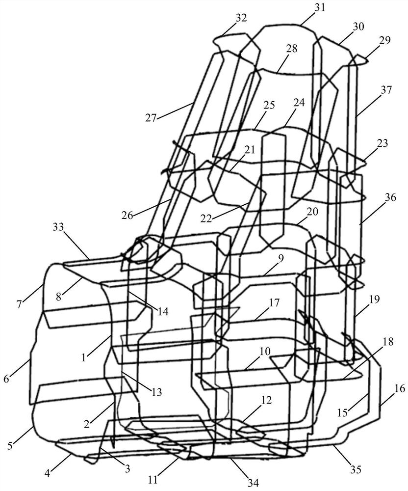
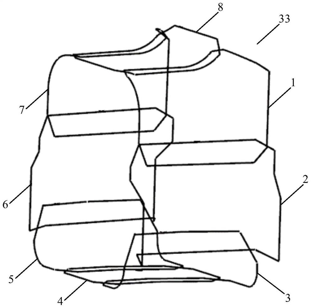
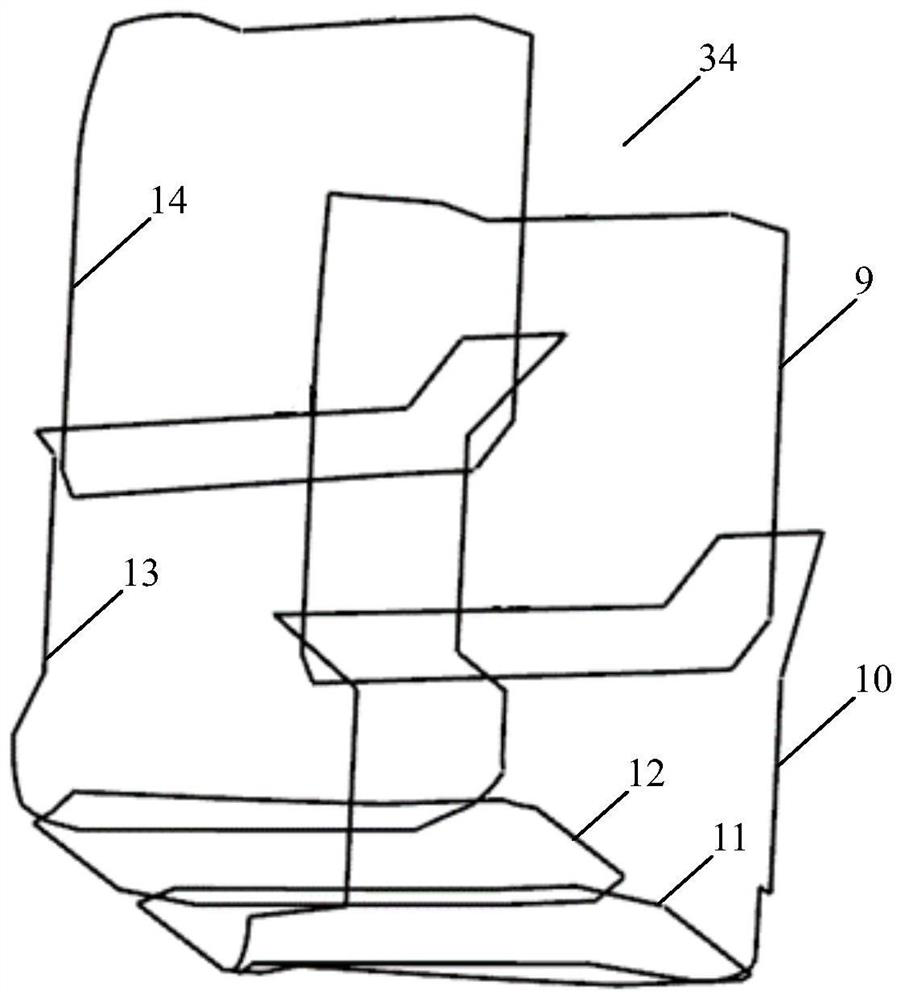
[0050] See Figure 1 to Figure 10 As shown, in a specific embodiment of the present invention, the 32-channel foot radio frequency receiving coil device for magnetic resonance imaging of the present invention includes ankle radio frequency receiving coil sub-assembly 33, ankle radio frequency receiving coil sub-assembly 34, heel radio frequency receiving coil sub-assembly Receiving coil sub-assembly 35, sole radio frequency receiving coil sub-assembly 36 and toe radio frequency receiving coil sub-assembly 37, wherein:

[0051] Described ankle radio frequency receiving coil sub-assembly 33 comprises the first channel 1, the second channel 2, the third channel 3, the fourth channel 4, the fifth channel 5, the sixth channel 6, the seventh channel all arranged along the left and right direction 7 and the eighth channel 8, the first channel 1, th...


PUM


Abstract

The invention provides a 32-channel foot radio frequency receiving coil device for magnetic resonance imaging. The device comprises an ankle joint radio frequency receiving coil sub-device, an ankle radio frequency receiving coil sub-device, a heel radio frequency receiving coil sub-device, a sole radio frequency receiving coil sub-device and a toe radio frequency receiving coil sub-device, and ischaracterized in that eight channels are mutually overlapped end to end in the left-right direction to form a first annular ring; six channels are sequentially arranged in an overlapped mode in the left-right direction to form a first U-shaped ring. Four half channels are sequentially arranged in an overlapped mode in the left-right direction to form a second U-shaped ring, the right end of the second U-shaped ring is sealed through one half channel, and six channels are arranged in an overlapped mode in the vertical direction to form a second annular ring and a third annular ring. The 32-channel foot radio frequency receiving coil device for magnetic resonance imaging has a higher signal-to-noise ratio and more uniform signal distribution, can improve the scanning coverage range, image quality and image uniformity of human feet, can improve the screening and diagnosis rate of foot diseases, and is ingenious in design, simple in structure, easy and convenient to manufacture and low incost.

Description

technical field [0001] The present invention relates to the technical field of medical devices, in particular to the technical field of magnetic resonance imaging systems, in particular to a 32-channel foot radio frequency receiving coil device for magnetic resonance imaging. Background technique [0002] The basic principle of magnetic resonance imaging (MRI) comes from the discovery of American scholars Bloch and Purcell in 1946 that under the action of an external magnetic field, certain spin protons (including hydrogen protons in the human body) that precess around the main magnetic field (external magnetic field) Under the action of short radio frequency waves, the precession angle increases. When the radio frequency waves stop, those protons will gradually return to their original state, and at the same time release radio frequency signals with the same frequency as the excitation wave. This physical phenomenon is called NMR. Magnetic resonance imaging technology uses...

Claims


Application Information

Patent Timeline
Patent Type & Authority Applications(China)
IPC IPC(8): G01R33/36A61B5/055
CPCG01R33/36A61B5/055
Inventor 邓华琼顾丽萍张松涛
Owner SHANGHAI CHENGUANG MEDICAL TECH
Learn More