Lightning protection device for power transformer

A technology for power transformers and lightning protection devices, applied in corona discharge devices, transformer/inductor components, circuits, etc., can solve the problems of affecting lightning protection effect, transformer installation obstruction, lightning strike damage to power transformers, etc., to avoid overcurrent Large, avoid bending, increase the effect of service life

Active Publication Date: 2021-07-23
广东龙标检测科技有限公司
View PDF0 Cites 0 Cited by
  • Summary
  • Abstract
  • Description
  • Claims
  • Application Information

AI Technical Summary

Problems solved by technology

Because the power transformer is mainly installed outdoors, and the outdoor environment is relatively harsh, it is very easy to cause the power transformer to be struck by lightning in the hot summer, resulting in lightning damage
[0003] In order to prevent the power transformer from being damaged by lightning, the power transformer currently in use generally installs a lightning rod on the top of the transformer and guides the lightning into the earth through the wire at the bottom of the lightning rod. In actual use, the structure of the lightning rod installed on the transformer is relatively simple. , when it is in use, because the voltage of the lightning strike is extremely large, after the tip of the lightning rod is discharged, the current that the wire at the bottom of the lightning rod bears is too large, which can easily lead to damage to the wire. However, there is no device for reducing the current in the existing device. lower lifespan
[0004] The installation process of the power transformer is relatively restricted by the environment, and the lightning rods installed in the existing power transformers are generally of the same specification, that is, the height is uniform, which is very easy to cause the transformer to The installation is hindered, and the height of the lightning rod cannot be adjusted in the existing device, which is inconvenient to use
[0005] In order to provide a better lightning guiding function, lightning rods are generally composed of metal parts with sharper tips, and generally have a higher height. Its center of gravity is also high, resulting in poor stability and bending deformation of the lightning rod, which not only affects the life of the lightning rod but also affects its lightning protection effect

Method used


Image

  • Lightning protection device for power transformer
  • Lightning protection device for power transformer
  • Lightning protection device for power transformer

Examples


Embodiment Construction

[0023] The following will clearly and completely describe the technical solutions in the embodiments of the present invention with reference to the accompanying drawings in the embodiments of the present invention. Obviously, the described embodiments are only some, not all, embodiments of the present invention. Based on the embodiments of the present invention, all other embodiments obtained by persons of ordinary skill in the art without making creative efforts belong to the protection scope of the present invention.

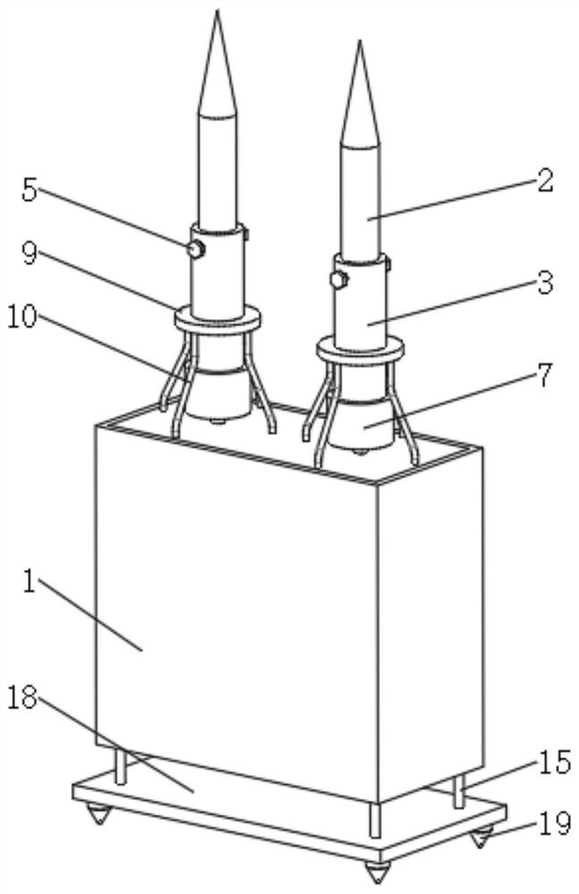
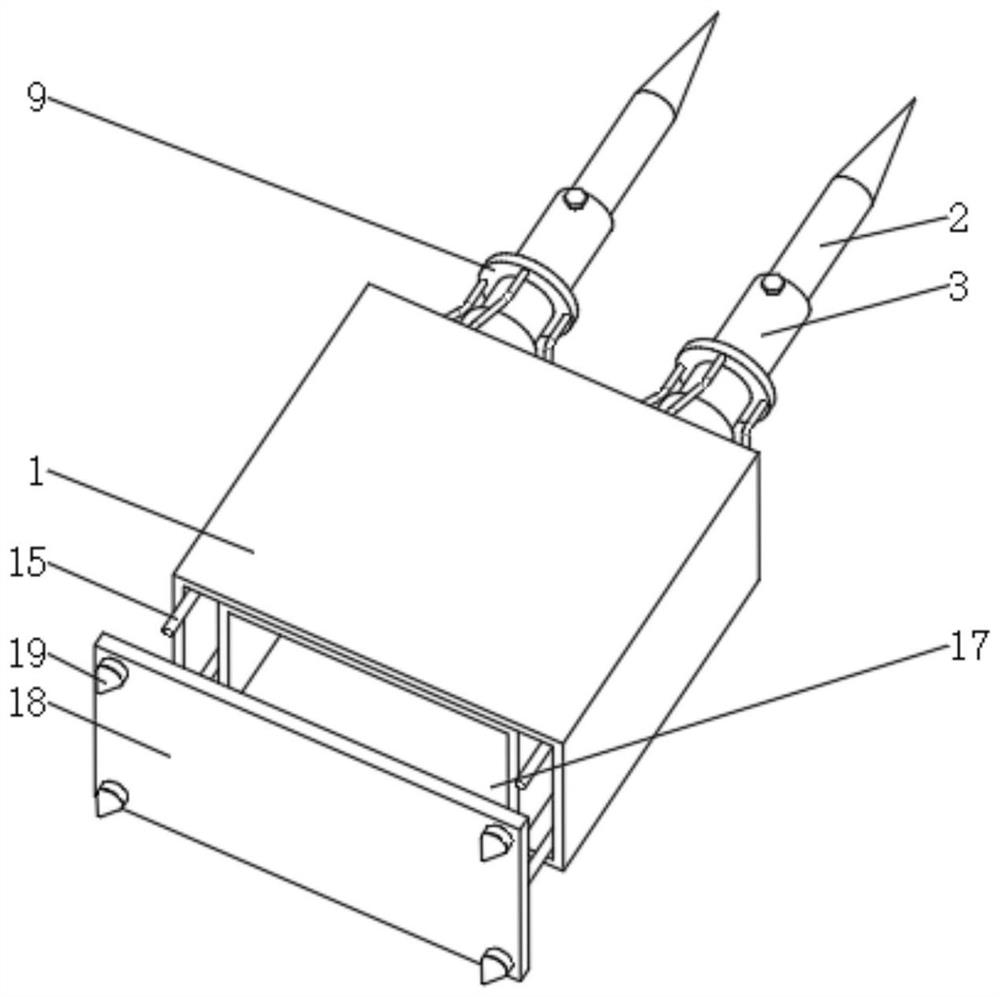
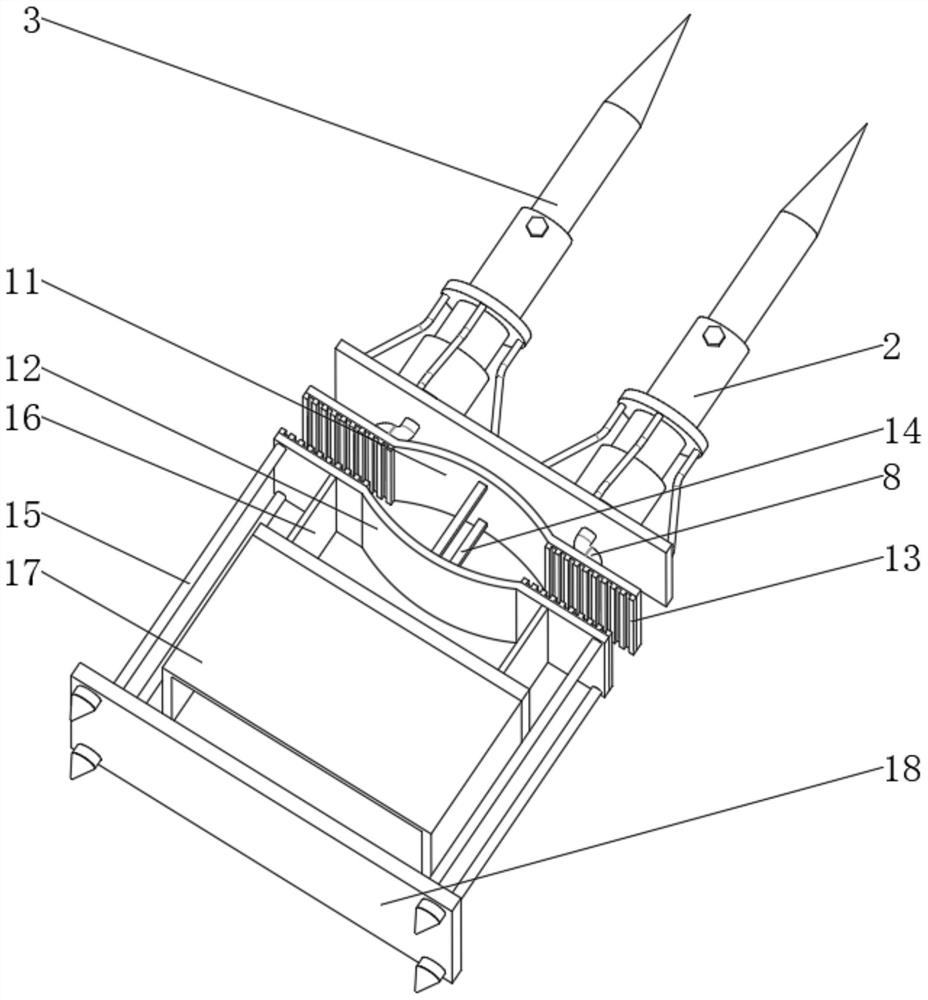
[0024] see Figure 1-5 , a power transformer lightning protection device, including a box 1, the left and right sides of the top of the box 1 are provided with a main pin 2, the bottom of the main pin 2 is fixedly installed with a base 7, and the bottom of the base 7 is fixedly installed with a main wire 8. The bottom end of the main wire 8 runs through the top of the inner cavity of the box body 1, and the upper pole plate 11 is fixedly installed on the posit...


PUM


Abstract

The invention relates to the technical field of lightning protection devices, and discloses a lightning protection device for power transformers, which includes a box body, main pins are arranged on the left and right sides of the top of the box body, and the bottom end of the main pins is fixedly installed with a base, so that The bottom end of the base is fixed with a main wire, and the bottom end of the main wire runs through the top of the box cavity. In this power transformer lightning protection device, the main wire is fixed at the bottom of the main needle and runs through the top of the box. When the top of the auxiliary needle is struck by lightning, the current can be introduced to the main needle through the auxiliary needle. The wire at the bottom of the base is introduced into the upper plate, and at the same time, it can also be introduced into the lower plate through the conductive column. At this time, the resistance plate on the opposite side of the upper plate and the lower plate can also provide greater resistance to reduce current consumption. The current is small, and finally led out through the auxiliary wire at the bottom of the lower plate, so as to avoid the excessive current of the wire, thereby realizing the advantage of increasing the service life of the wire.

Description

technical field [0001] The invention relates to the technical field of lightning protection devices, in particular to a lightning protection device for power transformers. Background technique [0002] A power transformer is a static electrical device that is used to change an AC voltage (current) of a certain value into another voltage (current) with the same frequency or several different values. When the primary winding is supplied with alternating current, alternating magnetic flux is generated, and the alternating magnetic flux induces an alternating electromotive force in the secondary winding through the magnetic conduction of the iron core. The level of the secondary induced electromotive force is related to the number of turns of the primary and secondary windings, that is, the voltage is proportional to the number of turns. The main function is to transmit electric energy, therefore, the rated capacity is its main parameter. Since the power transformer is mainly ...

Claims


Application Information

Patent Timeline
Patent Type & Authority Patents(China)
IPC IPC(8): H01F27/40H01F27/34H01T19/04H01R4/66
CPCH01F27/34H01F27/402H01R4/66H01T19/04
Inventor 闫山
Owner 广东龙标检测科技有限公司
Why Eureka
Try Eureka