Permanent magnet motor high rotating speed current limiting circuit

A permanent magnet motor and current-limiting circuit technology, which is applied in the direction of emergency protection circuit devices, electrical components, etc., can solve problems such as fuse blown, system capacitor damage, etc., and achieve the effects of fast switching speed, large current withstand, and stable circuit performance

Active Publication Date: 2012-08-08
福州欣联达电子科技有限公司
View PDF0 Cites 0 Cited by
  • Summary
  • Abstract
  • Description
  • Claims
  • Application Information

AI Technical Summary

Problems solved by technology

[0002] With the development of existing electric energy technology, the technology of electric vehicles is becoming more and more mature in response to the requirements of energy saving and environmental protection. Overcurrent and overvoltage charging of the battery can lead to system capacitor damage or fuse blown problems.

Method used


Image

  • Permanent magnet motor high rotating speed current limiting circuit
  • Permanent magnet motor high rotating speed current limiting circuit

Examples


Embodiment Construction

[0007] The present invention will be further described below in conjunction with the accompanying drawings and implementation examples.

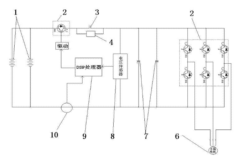
[0008] Such as figure 1 As shown, the present invention provides a high-speed current-limiting circuit for a permanent magnet motor, including a power battery or a supercapacitor battery 1, characterized in that: the output terminal of the power battery or supercapacitor battery 1 is connected to an IGBT module 2 via an The current limiting resistor 4 is connected, and the two ends of the current limiting resistor 4 are connected with the relay 3 controlled by the DSP processor, and the output terminal of the current limiting resistor 4 supplies power to the permanent magnet motor 6 through the charging capacitor 7 and the IGBT module 2 , the output end of the DSP processor is connected to the IGBT module 2 through an IGBT module drive circuit; the DSP processor is also connected with a current sensor 10 for measuring the supply current of t...


PUM


Abstract

The invention relates to a permanent magnet motor high rotating speed current limiting circuit. The circuit comprises a power battery or a super capacitor battery and is characterized in that: the output end of the power battery or the super capacitor battery is connected with a current limiting resistor through an IGBT module; the two ends of the current limiting resistor are in parallel connection with relays which are controlled by a DSP (digital signal processor); the output end of the current limiting resistor supplies power to a permanent magnet motor through a charging capacitor and the IGBT module; the output end of the DSP is connected with the IGBT module through an IGBT module drive circuit; and the DSP is also connected with a current sensor used for measuring the supply current of the permanent magnet motor. The permanent magnet motor high rotating speed current limiting circuit is mainly used for limiting the current of a high rotating speed of the permanent magnet motordriven by a mixed power and pure electric vehicle, and can effectively solve the problem of damaging a capacitor or a battery or burning a fuse caused by charging the super capacitor battery or the power battery under the condition of over-current or over-voltage because of the over-voltage phenomenon of the permanent magnet motor when a vehicle is in a high-speed running process or a high-speed sloping down process.

Description

technical field [0001] The invention relates to a high-speed current-limiting circuit for a permanent magnet motor, in particular to a high-speed current-limiting circuit for an electric vehicle permanent magnet motor. Background technique [0002] With the development of existing electric energy technology, the technology of electric vehicles is becoming more and more mature in response to the requirements of energy saving and environmental protection. The charging of the battery with overcurrent and overvoltage will cause damage to the system capacitor or blown fuse. Contents of the invention [0003] In view of the above problems, the purpose of the present invention is to provide a high-speed current limiting circuit for permanent magnet motors, which is mainly used for current limiting of high-speed permanent magnet motors driven by hybrid power and pure electric vehicles. During the process, the generator voltage of the permanent magnet motor is overvoltage, and th...

Claims


Application Information

Patent Timeline
Patent Type & Authority Patents(China)
IPC IPC(8): H02H7/18H02H7/16
Inventor 林钦陈沈明陈旭航陈杰
Owner 福州欣联达电子科技有限公司
Why Eureka
Try Eureka