Inserting needle contact part with spring for heat inserting and pull-out

A pin contact and strip spring technology, applied in the field of hot-swappable spring pin contacts, can solve problems such as contact performance limitations, connection failures, accidents, etc., achieve stable dynamic contact resistance, facilitate management and production, The effect of withstanding large current

Inactive Publication Date: 2006-03-29
CHINA AVIATION OPTICAL-ELECTRICAL TECH CO LTD
View PDF1 Cites 0 Cited by
  • Summary
  • Abstract
  • Description
  • Claims
  • Application Information

AI Technical Summary

Problems solved by technology

[0004] There are following deficiencies in this twisted wire pin structure: (1) because the twisted wire pin is an elastic pin made of a bunch of elastic metal wires twisted together, its rigidity is poor, and it will be damaged when it is inserted into a rigid jack. Due to the bending and deformation of the elastic pins, they are damaged by force, causing connection failures and accidents; (2) Since the twisted wire pins are elastic pins, the dimensions during processing cannot be guaranteed to be consistent, which affects the consistency of insertion and withdrawal forces; (3) Processing The process is complex and the precision requirements are high, resulting in low product qualification rate and high cost; (4) It can be seen from the structure of the stranded wire pin that the elastic metal wire cannot be very thick, making it difficult for each wire to withstand the impact of a large current; (5) The "crowding" phenomenon of twisted wire pins during use cannot be overcome
[0006] The disadvantage of this structure is that when the pin with the coil spring is inserted into the rigid socket, the metal strip of the coil spring is only in contact with the inner surface of the socket at the apex of the drum waist, which cannot make the entire metal strip tightly Braces are attached to the inner surface of the rigid socket, and their contact performance is limited

Method used


Image

  • Inserting needle contact part with spring for heat inserting and pull-out
  • Inserting needle contact part with spring for heat inserting and pull-out
  • Inserting needle contact part with spring for heat inserting and pull-out

Examples


Embodiment Construction

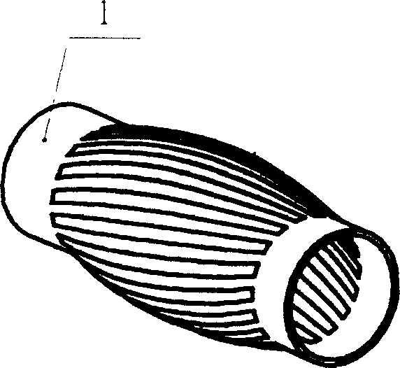
[0035] figure 1Shown is the "coil spring" figure shown in the accompanying drawing of the patent application publication number: CN1144020A "Connector for quick connection and disconnection". It can be seen from the figure that it is cylindrical, and the side wall is divided into A number of metal strips connected at both ends and perpendicular to the end surface are bent outwards into a bulging waist shape, showing a structure with small ends and a large middle.

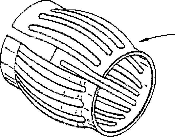
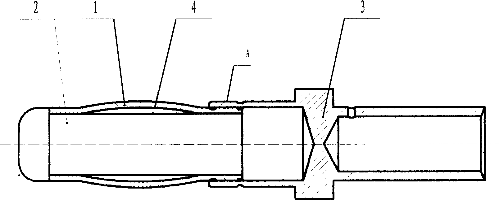
[0036] figure 2 The shown hot-swappable spring pin contact is composed of 4 sets of cylindrical rigid needle body 2 with a helical spring coil 1 in the middle annular groove, one end of which is embedded in the cylindrical blind hole on the end surface of the rear sleeve 3 , so that one end of the helical coil 1 is just clamped by the inner cylindrical surface of the blind hole of the rear sleeve 3 and the outer cylindrical surface of the rigid needle body 2, and the blind hole port of the rear sleeve 3 shrinks to...


PUM


Abstract

This invention discloses a hot plugging band spring contact pin and a screw band spring coil among which, the hot plugging band spring contact pin is composed of a screw band spring coil, a rigid pin and a rear jacket which can be used in different fields since it applies different leading and fixing ways. The main contact part of the screw band spring coil of the pin is formed by rolling a metal spring plate after punching and the screw band spring coil is in a screw curve contact way contacting with rigid plug holes in multiface envelope.

Description

Technical field [0001] The invention belongs to electrical connector contacts, in particular to a hot-swappable spring pin contact. Background technique [0002] The electrical connector is an electronic device with a wide range of applications. Its core is a contact couple composed of a pin contact and a socket contact. Reliable contacts to complete. In order to make the pin contact and the socket contact have better contact performance, one end is designed as an elastic contact. [0003] At present, most of the existing electrical connector contact couples are elastic sockets matched with rigid pins. The use of rigid jacks and elastic pins can reduce the size of the jacks and pins without reducing the contact performance, simplify the structure, and make it easier to manufacture. In the prior art, the existing elastic pin contacts with better reliability and stability are twisted wire pins, which process a bundle of elastic metal wires wound together into a bulging wais...

Claims


Application Information

Patent Timeline
Patent Type & Authority Patents(China)
IPC IPC(8): H01R13/05H01R13/33
Inventor 吕永锋
Owner CHINA AVIATION OPTICAL-ELECTRICAL TECH CO LTD
Why Eureka
Try Eureka