Display panel and display device

A technology for display panels and substrate substrates, which is applied in the fields of instruments, acquisition/organization of fingerprints/palmprints, electric solid-state devices, etc., can solve the problems such as the inability to meet the requirements of the transmittance of fingerprint recognition under the screen and the low transmittance, etc. Achieve the effect of avoiding affecting the accuracy of fingerprint collection, reducing reflectivity, and reducing reflectivity

Pending Publication Date: 2021-01-22
BOE TECH GRP CO LTD +1
View PDF4 Cites 5 Cited by
  • Summary
  • Abstract
  • Description
  • Claims
  • Application Information

AI Technical Summary

Problems solved by technology

[0003] However, when the under-screen fingerprint recognition technology is applied to an organic light-emitting display (Organic Light-Emitting Diode, OLED) based on COE (CFon EL, a color filter layer is formed on a thin-film-encapsulated organic electroluminescent device), due to the black matrix ( Black Matrix, BM), color filter layer (Color Filter, CF) and the shielding of the electrode layer, the light transmittance of the COE-based OLED is very low, which cannot meet the transmittance requirements for fingerprint recognition under the screen

Method used


Image

  • Display panel and display device
  • Display panel and display device
  • Display panel and display device

Examples


Embodiment Construction

[0037] Example embodiments will now be described more fully with reference to the accompanying drawings. Example embodiments may, however, be embodied in many forms and should not be construed as limited to the embodiments set forth herein; rather, these embodiments are provided so that this disclosure will be thorough and complete, and will fully convey the concept of example embodiments to those skilled in the art. The same reference numerals in the drawings denote the same or similar structures, and thus their detailed descriptions will be omitted.

[0038] Although relative terms such as "upper" and "lower" are used in this specification to describe the relative relationship of one component of an icon to another component, these terms are used in this specification only for convenience, for example, according to the description in the accompanying drawings directions for the example described above. It will be appreciated that if the illustrated device is turned over so...


PUM


Abstract

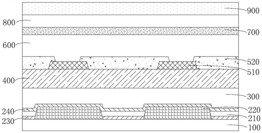
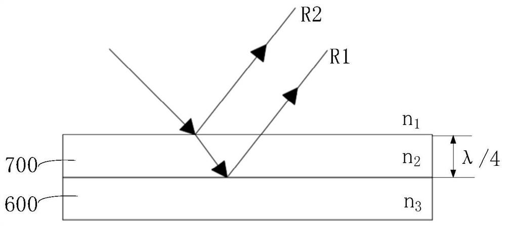
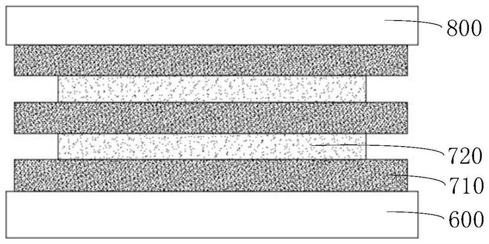
The invention provides a display panel and a display device, and the display panel comprises a substrate, a first electrode layer, a pixel defining layer, a light-emitting layer, a second electrode layer, a packaging layer, a black matrix, a color film layer, a covering layer, a reflection reducing function layer, and an optical adhesive layer. The first electrode layer and the pixel defining layer are arranged on one side of the substrate; the light-emitting layer is arranged on the side, deviating from the substrate body, of the first electrode layer, the second electrode layer covers the sides, deviating from the substrate body, of the pixel defining layer and the light-emitting layer, the packaging layer is arranged on the side, deviating from the substrate body, of the second electrode layer, and the black matrix and the color film layer are arranged on the side, deviating from the substrate body, of the packaging layer; the covering layer covers the sides, deviating from the underlayer substrate, of the black matrix and the color film layer, the reflection reducing functional layer is arranged on the side, deviating from the underlayer substrate, of the covering layer and configured to reduce the reflectivity of external incident light, and the optical adhesive layer is arranged on the side, deviating from the underlayer substrate, of the reflection reducing functional layer. According to the display panel provided by the invention, the overall reflectivity of a product can be reduced.

Description

technical field [0001] The present disclosure relates to the field of display technology, and in particular, to a display panel and a display device. Background technique [0002] With the development of terminal technology, the screen size of electronic devices is getting larger and larger, and electronic devices with a high screen-to-body ratio are gradually favored by users. As the ultimate development of high-screen-to-body electronic devices, full-screen electronic devices maximize the screen ratio of electronic devices. It is one of the most popular technologies at present and is loved and sought after by users. In order to keep the fingerprint collection module on the display surface of the electronic device and avoid affecting the screen-to-body ratio of the electronic device, an under-screen fingerprint recognition method is proposed in the prior art to realize the fingerprint recognition function. Compared with the traditional fingerprint recognition module, the f...

Claims


Application Information

Patent Timeline
IPC IPC(8): H01L51/52H01L27/32G06K9/00
CPCG06V40/1318H10K59/60H10K59/38H10K50/858
Inventor 杨超陈立强李振东庞孟媛杨恕权
Owner BOE TECH GRP CO LTD
Why Eureka
Try Eureka