
Continuous roller cleaning machine

A washing machine and drum technology, which is applied to dryers, conveyors, cleaning methods and appliances, etc., can solve problems such as difficult cleaning in place, poor cleaning quality of parts, and low cleaning efficiency, so as to solve the problems of parts bonding, Cleaning without dead ends and improving cleaning efficiency

Pending Publication Date: 2021-01-26
HUBEI HAPM MAGNA SEATING SYST CO LTD
View PDF0 Cites 2 Cited by
  • Summary
  • Abstract
  • Description
  • Claims
  • Application Information

AI Technical Summary

Problems solved by technology

[0005] On the one hand, the step-by-step solution uses the loading of the material frame. There are stacks of parts in the material frame, and there are bonding areas between parts. These bonding areas are not easy to clean during cleaning, resulting in poor cleaning quality of the parts.
[0006] On the other hand, the step-by-step scheme is affected by the "short board effect", and the working time of each step needs to be consistent, resulting in low cleaning efficiency

Method used


Image

  • Continuous roller cleaning machine
  • Continuous roller cleaning machine
  • Continuous roller cleaning machine

Examples


Embodiment Construction

[0047] In order to enable those skilled in the art to better understand the solution of the present invention, the present invention will be further described in detail below in conjunction with the accompanying drawings and specific embodiments.

[0048] In this article, terms such as "upper, lower, left, right" are established based on the positional relationship shown in the drawings, and the corresponding positional relationship may also change accordingly depending on the drawings. It is understood as an absolute limitation on the scope of protection; moreover, relative terms such as "first" and "second" are only used to distinguish one from another component with the same name, and do not necessarily require or No such actual relationship or order between these components is implied.

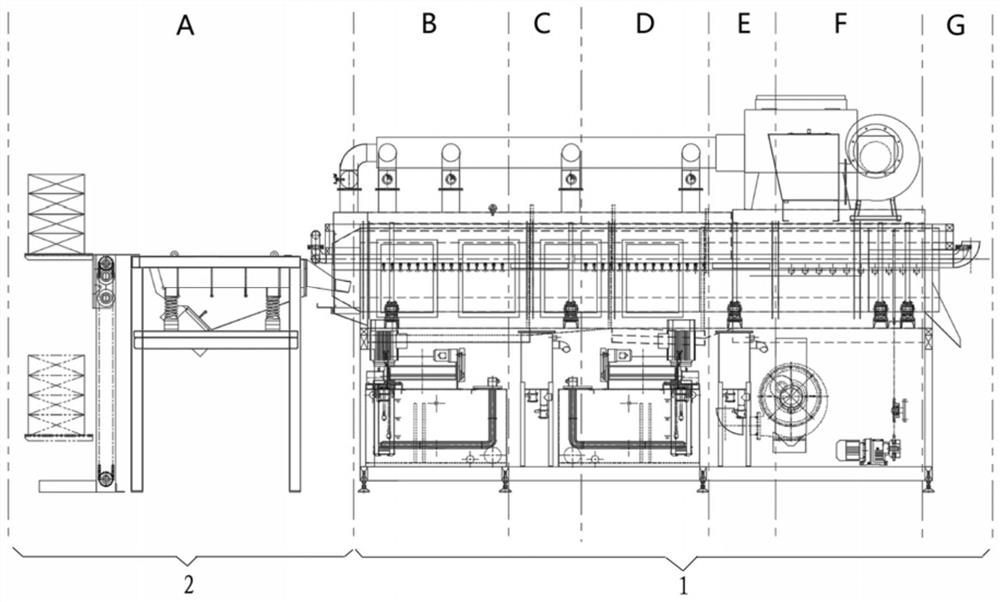
[0049] Please refer to figure 1 , figure 1 It is a structural schematic diagram of a continuous drum cleaning machine disclosed in an embodiment of the present invention.

[0050]As sho...


PUM


Abstract

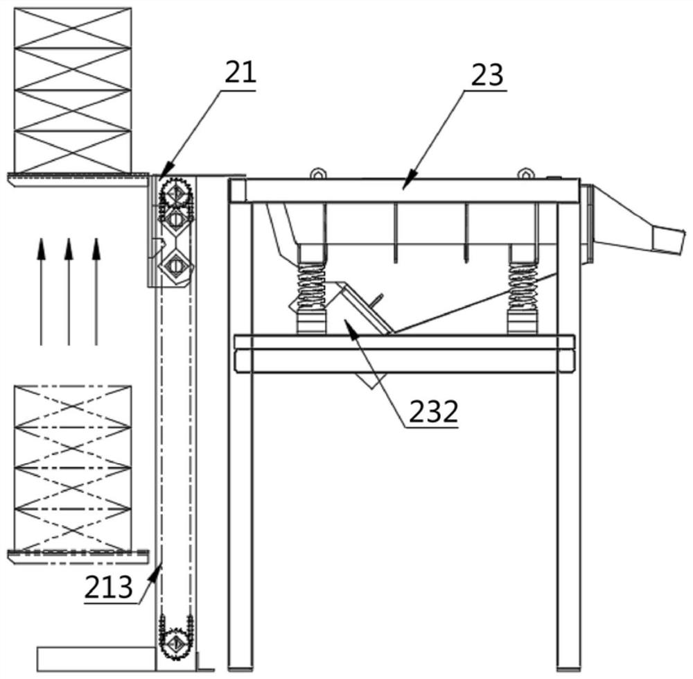
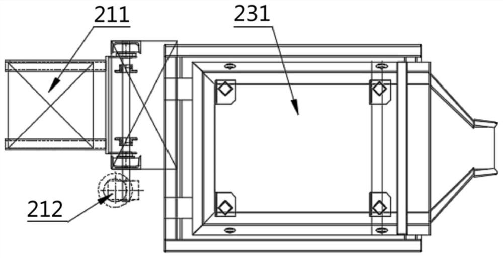
The invention discloses a continuous roller cleaning machine. The continuous roller cleaning machine comprises a cleaning machine body (1) and a feeding system (2), wherein the cleaning machine body (1) is provided with a conveying system (3) used for conveying a to-be-cleaned part in the axial direction, and a cleaning system (4), a first wind shearing system (5), a rinsing system (6), a second wind shearing system (7) and a drying system (8) are sequentially arranged along a conveying path of the conveying system (3); the conveying system (3) comprises a roller (31) and a driving motor (32),and the driving motor (32) is in transmission connection with the roller (31) in order to drive the roller (031) to rotate; a through hole (36) is arranged in the roller wall of the roller (31), anda spiral piece (37) capable of driving the to-be-cleaned piece to move along the conveying path is arranged on the inner wall of the roller (31). The cleaning machine solves the part fitting problem,the appearance quality is high after cleaning is completed, and the cleaning efficiency can be remarkably improved.

Description

technical field [0001] The invention relates to the technical field of cleaning equipment for fine blanking parts, in particular to a continuous drum cleaning machine for washing fine blanking parts to remove fine blanking oil attached thereto. Background technique [0002] In the production process of fine blanking parts, fine blanking oil is usually used for lubrication between the fine blanking die and fine blanking parts, so that a layer of fine blanking oil will be attached to the surface of the produced fine blanking parts, and the density of fine blanking oil is slightly higher than that of water , the kinematic viscosity at 40°C can reach more than 100mm2 / s, and the adhesion is strong, which will affect the appearance quality of the product and the post-process treatment (such as heat treatment), so the surface of the fine blanking parts needs to be cleaned after the fine blanking process is completed. [0003] At present, small fine blanking parts are generally clea...

Claims


Application Information

Patent Timeline
IPC IPC(8): B08B3/02B08B3/06B08B3/08B08B3/10B65G17/12B65G65/44B65G69/04F26B21/00F26B21/04F26B25/00
CPCB08B3/022B08B3/06B08B3/08B08B3/10B08B2203/007B65G17/12B65G65/44B65G69/0425F26B21/001F26B21/004F26B21/04F26B25/006
Inventor 陶峰吴楚秦妮
Owner HUBEI HAPM MAGNA SEATING SYST CO LTD
Learn More