Pressing equipment for assembly

A technology of pressing equipment and hydraulic mechanism, which is applied in the field of stamping, can solve problems such as loud noise, replacement of mold templates, and large vibration, and achieve the effects of reducing pressure, increasing force-bearing area, and saving costs

Inactive Publication Date: 2021-01-26
南京冉科信息技术有限公司
View PDF0 Cites 0 Cited by
  • Summary
  • Abstract
  • Description
  • Claims
  • Application Information

AI Technical Summary

Problems solved by technology

[0004] The purpose of the present invention is to solve the shortcomings in the prior art, such as the inability to replace the mold template with the same equipment, the vibration is too large, the noise is too large, etc.

Method used


Image

  • Pressing equipment for assembly
  • Pressing equipment for assembly
  • Pressing equipment for assembly

Examples


Embodiment 1

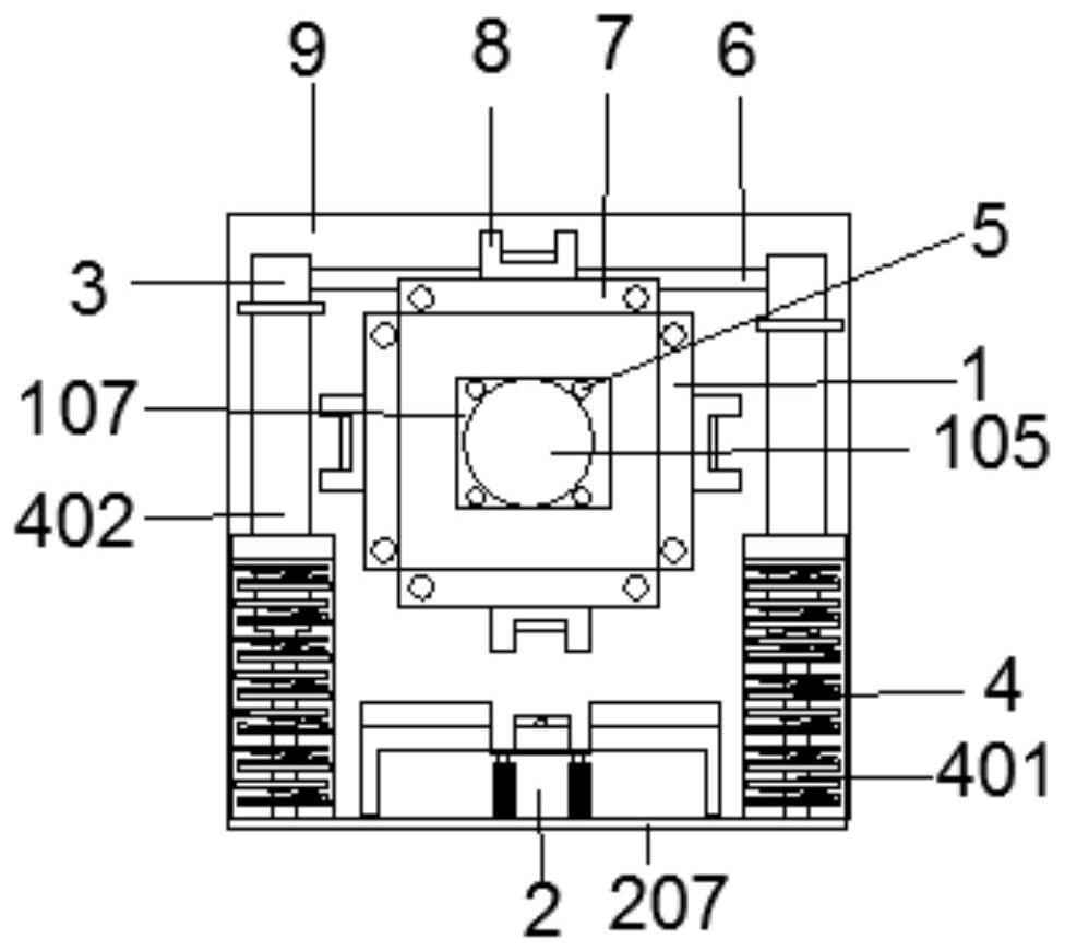
[0023] Example 1, such as Figure 1-3 As shown, a pressing device for assembly includes a body 9, a rotating mechanism 1, a shock absorbing mechanism 2 and a hydraulic mechanism 3;

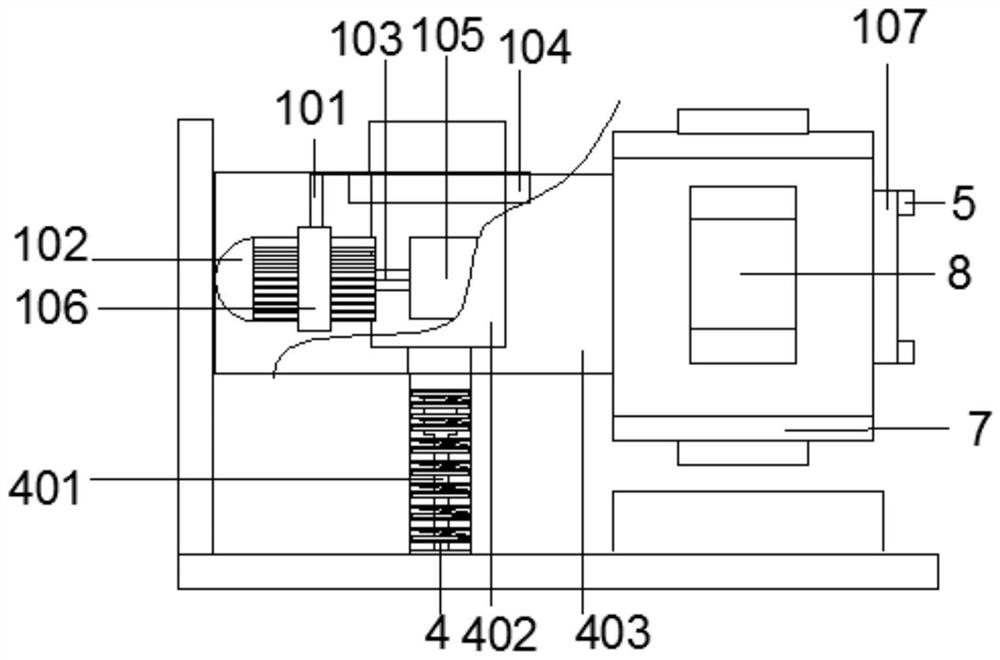
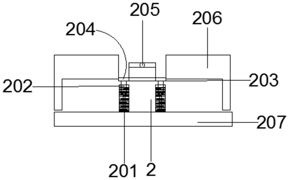
[0024] The rotating mechanism 1 comprises a DC motor 102 and a connection block 105, the right side of the DC motor 102 is rotatably connected with a rotating shaft 103, the right side of the connection block 105 is fixedly connected with a washer 107 by four screws 5, and the outer surface of the connection block 105 right side is surrounded by Both are fixedly connected with an iron plate 7, the outer surface of the iron plate 7 is fixedly connected with a template 8, the shock absorbing mechanism 2 includes a metal plate 207 and a metal block 206, and both sides of the top of the metal plate 207 are fixedly connected with shock absorbing springs 201, The top of the metal plate 207 is fixedly connected with a pillar 202 , the pillar 202 is embedded in the interior of the shock absorbing spring 2...

Embodiment 2

[0026] Embodiment 2, the tops of the two backing plates 204 are fixedly connected with screws 203, the two backing plates 204 are screwed with torsion nails 205, the metal block 206 is fixedly connected on the top of the metal plate 207, and the hydraulic mechanism 3 includes a column 401 and The cabinet body 403 is fixedly connected with a hydraulic cylinder 402 at the top of the two columns 401, the two columns 401 are embedded in the inside of the damping spring 4, the cabinet body 403 is fixedly connected at the top of the two columns 401, and the two hydraulic cylinders 402 The outer surface close to the top is fixedly connected with a piston rod 104, and the side opposite to the top of the hydraulic cylinder 402 is fixedly connected with a connecting rod 6, and the bottom at the center of the connecting rod 6 is fixedly connected with the top of the cabinet body 403, and the outer surface of the DC motor 102 A ferrule 106 is fixedly sleeved at the center of the surface, a...


PUM


Abstract

The invention provides pressing equipment for assembly, and relates to the technical field of stamping dies. The pressing equipment comprises a machine body, a rotating mechanism, a damping mechanismand a hydraulic mechanism, wherein the rotating mechanism comprises a direct-current motor and a connecting block, the right side of the direct-current motor is rotatably connected with a rotating shaft, and the right side of the connecting block is fixedly connected with a gasket through four screws; and iron plates are fixedly connected to the periphery of the outer surface of the right side ofthe connecting block, templates are fixedly connected to the outer surfaces of the iron plates, and the damping mechanism comprises a metal plate and a metal block. According to the pressing equipment, the direct-current motor is fixedly connected to the top of the inner surface of the machine body through a supporting column and a ferrule, the rotating shaft is fixedly connected with the connecting block, an electronic product material is placed on a base plate, an external power source is turned on, the direct-current motor drives the rotating shaft to rotate, the rotating shaft drives the iron plates to rotate, molds are embedded in the tops of the iron plates, and the molds can be rotated according to own needs to press parts for electronic products.

Description

technical field [0001] The invention relates to the technical field of stamping, in particular to a pressing device for assembly. Background technique [0002] Pressing is a forming and processing method in which presses and molds apply external force to sheets, strips, pipes, and profiles to cause plastic deformation or separation, thereby obtaining pressed parts of the desired shape and size. Pressing and forging belong to pressure processing, collectively called forging. The pressed blanks are mainly hot-rolled and cold-rolled steel sheets and strips. Among the steel products in the world, 60-70% are plates, most of which are pressed into finished products. The body, chassis, fuel tank, radiator fins of the car, the steam drum of the boiler, the shell of the container, the iron core silicon steel sheet of the motor and electrical appliances, etc. are all pressed and processed. There are also a large number of press-fit parts in products such as instruments and meters, ...

Claims


Application Information

Patent Timeline
Patent Type & Authority Applications(China)
IPC IPC(8): B21D37/14B21D55/00B21D22/02F16F15/067
CPCB21D22/02B21D37/14B21D55/00F16F15/067
Inventor 王静
Owner 南京冉科信息技术有限公司
Why Eureka
Try Eureka