A kind of numerical control cutter and its manufacturing method

A manufacturing method and cutting tool technology, which is applied in the direction of manufacturing tools, metal processing equipment, maintenance and safety accessories, etc., can solve the problems of decreased precision of workpieces, fast loss of tools, increased industrial costs, etc., to increase sealing performance and reduce broken knives Phenomenon, the effect of weakening mechanical vibration

Active Publication Date: 2022-03-25
昆山长鹰硬质材料科技股份有限公司
View PDF11 Cites 0 Cited by
  • Summary
  • Abstract
  • Description
  • Claims
  • Application Information

AI Technical Summary

Problems solved by technology

[0002] Existing CNC tools have defects such as high noise, low finish, slow efficiency, fast tool loss, and low precision during processing, and the vibration of the tool during processing will cause the tool to be easily damaged. Once the tool is damaged, the tool needs to be reinstalled, not only Delayed working hours will also increase industrial costs and affect the production efficiency of enterprises. In addition, after the tool vibration acts on the mechanical workpiece, the precision of the workpiece will be greatly reduced.

Method used


Image

  • A kind of numerical control cutter and its manufacturing method
  • A kind of numerical control cutter and its manufacturing method
  • A kind of numerical control cutter and its manufacturing method

Examples


Embodiment 1

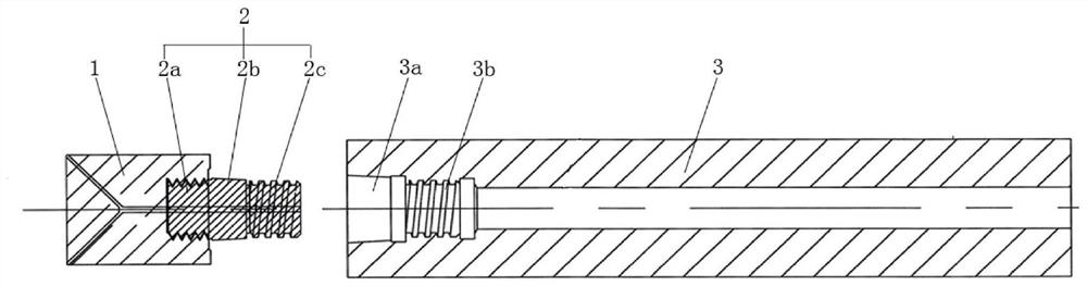
[0032] like figure 1 As shown, a numerical control tool includes a tool head 1, a tool shank 3 and a connecting piece 2 for connecting the tool head 1 and the tool shank 3, and the tool head 1, the tool shank 3 and the connecting piece 2 are arranged coaxially.

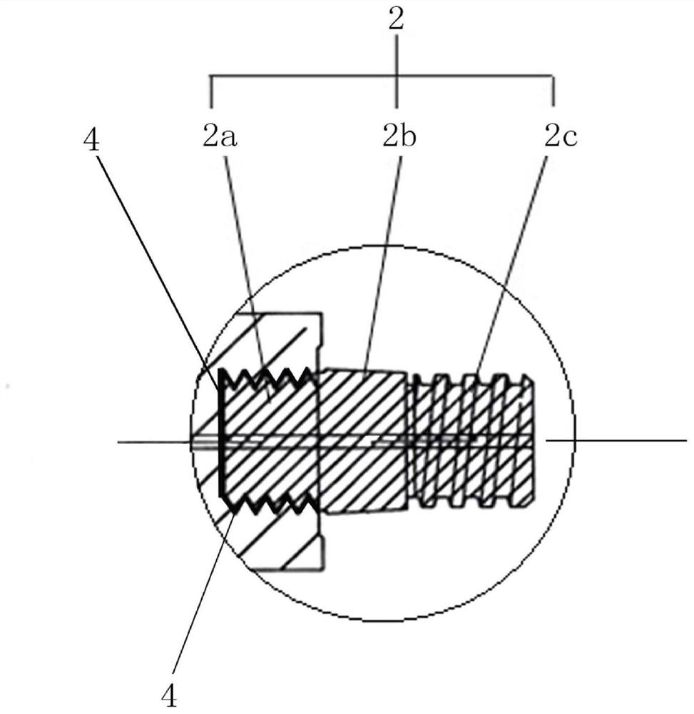
[0033] The connecting piece 2 includes a cutting head connecting section 2a and a cutting shank connecting section.

[0034] The cutter head connecting section 2a is provided with an external thread on the outer circumference, and the end of the cutter head 1 connected with the connecting piece 2 is provided with a cutter head connecting groove in the cutter head 1 along the axis of the cutter head 1, and the side wall of the cutter head connecting groove is provided with an inner thread , the inner thread is matched with the outer thread, and is used to connect the cutter head 1 to the connecting piece 2 . A shock-absorbing glue 4 is attached between the groove bottom and the side wall of the cutter head connecting ...

Embodiment 2

[0047] The embodiment of the present invention provides a method for manufacturing a numerically controlled tool, which can be used for processing and manufacturing the numerically controlled tool described in the first embodiment, which mainly includes the following steps:

[0048] Step 1: Select the cutter head 1 blank, and process the cutter head connecting groove along the axis direction of the cutter head 1 blank;

[0049] Step 2, machining an internal thread in the cutter head connecting groove, and the internal thread should be compatible with the external thread of the cutter head connecting section 2a;

[0050] Step 3: Pour the liquid shock-absorbing glue 4 into the connecting groove of the cutter head. Before the shock-absorbing glue 4 solidifies, install the connecting section 2a of the cutting head in the connecting groove of the cutting head. When installing, ensure that the cutting head 1 and the connecting piece are installed. 2, so that the shock-absorbing glue...


PUM


Abstract

The invention discloses a numerically controlled cutting tool and a manufacturing method thereof. The numerically controlled cutting tool includes a cutter head arranged on a coaxial line, a connecting piece and a cutter bar, and the connecting piece includes a connecting section of a cutter head and a connecting section of a knife bar; The connecting section of the head is threadedly connected with the cutter head, and shock-absorbing glue is filled between the connecting section of the cutter head and the cutter head; the connecting section of the knife rod includes a tapered section and a threaded section, and the The tapered connection portion of the segment interference fit and the threaded engagement portion engaged with the threaded segment. The numerically controlled cutting tool provided by the invention has better stability, higher processing precision and anti-shock performance.

Description

technical field [0001] The invention belongs to the technical field of numerical control machining, and in particular relates to a numerical control tool and a manufacturing method thereof. Background technique [0002] The existing CNC tools have defects such as loud noise, low finish, slow efficiency, fast tool wear, and low precision during processing, and the vibration of the tool during processing will cause the tool to be easily damaged. Once the tool is damaged, the tool needs to be reinstalled, not only Delayed working hours will also increase industrial costs and affect the production efficiency of enterprises. In addition, when the tool vibration acts on the mechanical workpiece, the precision of the workpiece will be greatly reduced. SUMMARY OF THE INVENTION [0003] The purpose of the present invention is to overcome the deficiencies in the prior art, and to provide a numerical control tool and a manufacturing method thereof, which have better stability, higher...

Claims


Application Information

Patent Timeline
Patent Type & Authority Patents(China)
IPC IPC(8): B23D79/00B23Q11/10B23P15/28
CPCB23D79/00B23Q11/10B23P15/28B23Q11/1023
Inventor 黄启君袁志勇梅小俊陈铭军谢慧
Owner 昆山长鹰硬质材料科技股份有限公司
Why Eureka
Try Eureka