Novel cooling type ceramic body applied to laser cutting head

A laser cutting head and ceramic body technology, applied in the laser field, can solve the problems of thin lock ring, poor nozzle cooling effect, small gas path, etc., and achieve uniform and efficient cooling

Pending Publication Date: 2021-01-26
苏州钋镭自动化科技有限公司
View PDF0 Cites 0 Cited by
  • Summary
  • Abstract
  • Description
  • Claims
  • Application Information

AI Technical Summary

Problems solved by technology

[0003] In view of this, in order to solve the problem that the thickness of the lock ring is thin and the whole structure is small, the air flow of the generated air path is small, which makes the cooling effect on the nozzle poor. This invention proposes a new cooling type applied to the laser cutting head. The ceramic body, the first air hole is opened at the corresponding position on the ceramic body and the conductive part, the outlet position of the second air hole of the conductive part is connected with the circular groove at the lower part of the conductive part, and the first air hole is connected with the second air hole to form the first gas path , the position of the cooling type ceramic body on the cutting head is located at the lower part of the capacitor head. The air path connects the nozzle under the ceramic body, and the gas flows in the circular groove and can be discharged from the gap around the conductive part and the nozzle to ensure uniform and efficient cooling of the nozzle

Method used


Image

  • Novel cooling type ceramic body applied to laser cutting head
  • Novel cooling type ceramic body applied to laser cutting head
  • Novel cooling type ceramic body applied to laser cutting head

Examples


Embodiment Construction

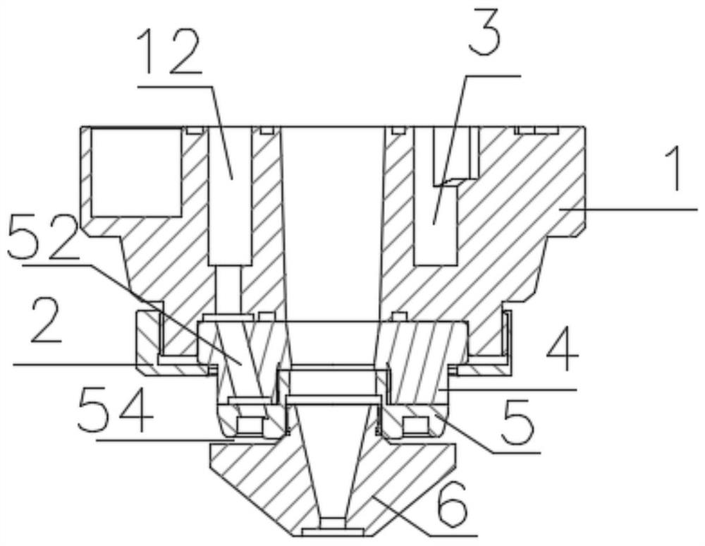
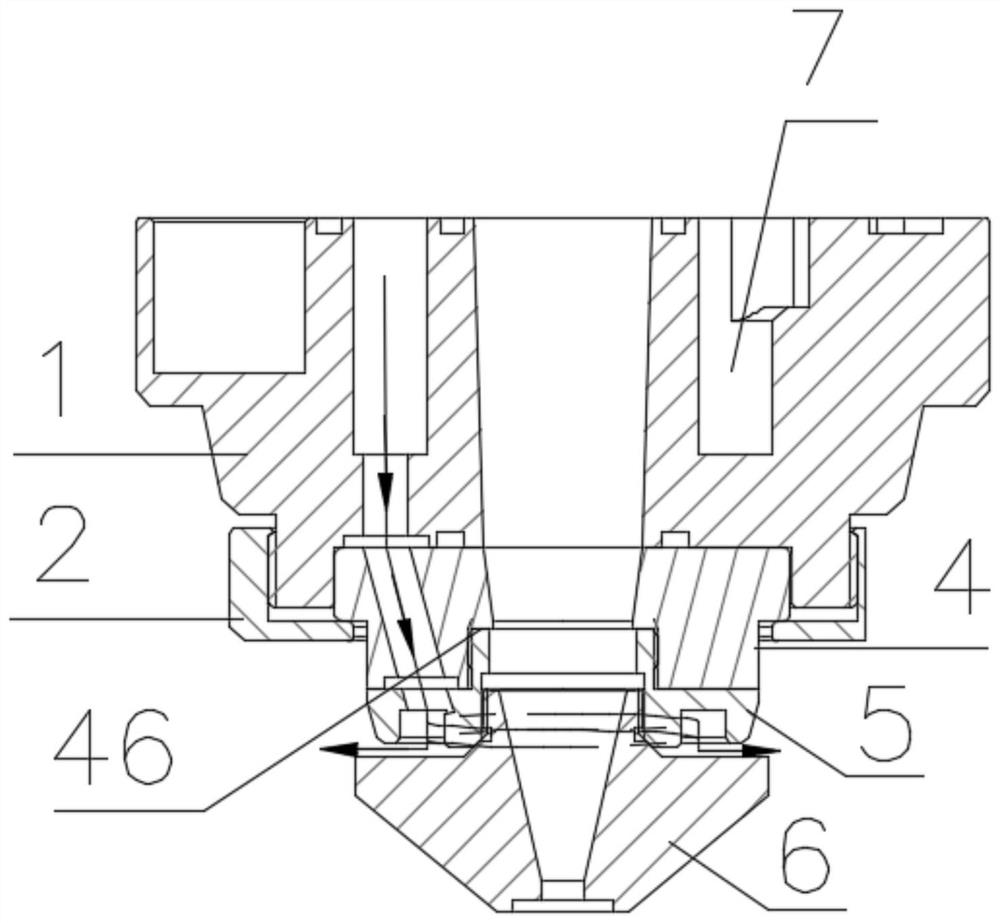
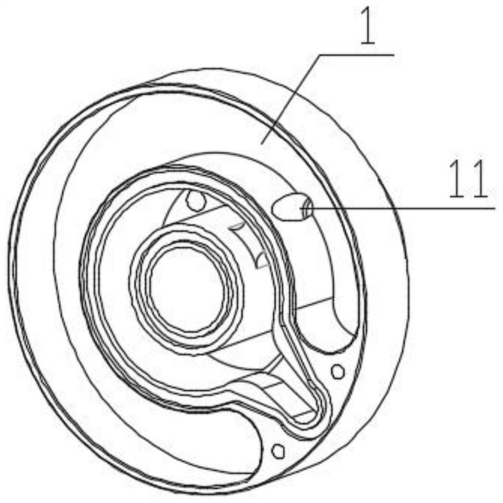
[0025] Such as figure 1 As shown, it is a sectional structure diagram of a novel cooling type ceramic body applied to a laser cutting head of the present invention; figure 2 Shown is the air flow profile structure diagram of the novel cooling type ceramic body applied to the laser cutting head of the present invention; image 3 As shown, it is a structural diagram of the capacitive head of the novel cooling type ceramic body applied to the laser cutting head of the present invention; Figure 4 Shown is the lock ring structure diagram of the novel cooling type ceramic body applied to the laser cutting head of the present invention; Figure 5 Shown is the ceramic body structural diagram of the novel cooling type ceramic body applied to the laser cutting head of the present invention; Image 6 As shown, it is a structural diagram of the conductive part of the novel cooling type ceramic body applied to the laser cutting head of the present invention; Figure 7 As shown, it is ...


PUM


Abstract

In order to solve the problems that the thickness of a locking ring is small, the whole structure is small, and generated gas flow of gas paths is small, and consequently the cooling effect to a nozzle is poor, the invention provides a novel cooling type ceramic body applied to a laser cutting head. A first gas hole is formed in the position, corresponding to a conductive part, of the elastic body. The position of an outlet of a second gas hole of the conductive part communicates with a circular groove in the lower portion of the conductive part, and the first gas hole communicates with the second gas hole to form a first gas path. The position, on the cutting head, of the cooling type ceramic body is located on the lower portion of a capacitor head, and the capacitor head is provided witha second gas path communicating with the first gas hole. Cooling gas flows into the second gas path at the corresponding position after passing through the second gas path of the capacitor head, a nozzle is connected to the lower portion of the ceramic body, gas flows in the circular groove and can be discharged from gaps around the conductive part and the nozzle, and it is guaranteed that the nozzle is cooled evenly and efficiently.

Description

technical field [0001] The invention relates to the field of lasers, and more specifically, relates to a cooling ceramic body on a laser cutting head. Background technique [0002] At present, the cooling method of the laser cutting head for the position of the nozzle is to open air holes on the lock ring of the lock ceramic body, and the air holes blow air to the nozzle for cooling. However, due to the thinner thickness of the lock ring and the smaller overall structure, the The air flow in the gas path is small, so this cooling method is not ideal for cooling the nozzle. The lock ring is connected to the edge of the ceramic body, the upper part of the ceramic body is connected to the capacitor head, and the lower part is connected to the nozzle of the laser cutting head. There is less space on the ceramic body. Large, the original function of the ceramic body is only to prevent the cutting head from being damaged when the cutting nozzle collides with other objects, so whet...

Claims


Application Information

Patent Timeline
Patent Type & Authority Applications(China)
IPC IPC(8): B23K26/70B23K26/38
CPCB23K26/38B23K26/703
Inventor 程伟
Owner 苏州钋镭自动化科技有限公司
Why Eureka
Try Eureka