Power conversion device

a power conversion device and power conversion technology, applied in the direction of solid-state devices, basic electric elements, electric apparatus construction details, etc., can solve the problems of becoming difficult to uniformly cool each affecting the cooling performance of the circuit element portions, so as to suppress the increase in the cooling performance, uniform and efficient cooling, and efficient cooling of the low side arm elements

Active Publication Date: 2020-10-06
HONDA MOTOR CO LTD
View PDF12 Cites 0 Cited by
  • Summary
  • Abstract
  • Description
  • Claims
  • Application Information

AI Technical Summary

Benefits of technology

[0006]An aspect of the present invention is contrived in view of such circumstances, and an object thereof is to provide a power conversion device which makes it possible to cool a plurality of elements uniformly and efficiently, and to suppress an increase in a difference in cooling performance between the plurality of elements.
[0011]According to the above (1), as compared with a case where a plurality of power conversion circuit portions are disposed on a refrigerant flow channel of one system, it is possible to suppress an increase in the temperature gradient of a refrigerant between the upstream side and the downstream side of the refrigerant flow channel associated with an increase in the number of power conversion circuit portions. In addition, since a branching flow channel is provided for each phase in the first motor and the second motor, it is possible to suppress a change in cooling performance among a plurality of phases of each motor, and to make cooling performance between a plurality of phases uniform.
[0012]Here, the first element array corresponding to the first motor has more of a tendency to generate heat than the second element array corresponding to the second motor. Therefore, in each of the first branching flow channels, the first element array is disposed further upstream than the second element array, and thus a difference in temperature between the refrigerant and the first element array has a tendency to be secured. Thereby, it is possible to uniformly and efficiently cool the first element array and the second element array, and to suppress an increase in a difference in cooling performance between a plurality of element arrays.
[0013]In a case of the above (2), in each of the first element array and the second element array in each branching flow channel, the high side arm element and the low side arm element are disposed side by side in the first direction, and thus it is possible to suppress an increase in a difference in cooling performance between the high side arm element and the low side arm element.
[0015]In the second branching flow channel, since the low side arm element is disposed on the upstream side of the high side arm element, it is possible to secure a difference in temperature between the refrigerant and the low side arm element. As a result, it is possible to efficiently cool the low side arm element. Thereby, it is possible to uniformly and efficiently cool the high side arm element and the low side arm element of the voltage conversion circuit, and to suppress an increase in a difference in cooling performance between the high side arm element and the low side arm element.

Problems solved by technology

As a result, it becomes difficult to uniformly cool each of the circuit element portions 101.
As a result, it becomes difficult to uniformly cool the circuit element portions 101 of each phase.

Method used


Image

  • Power conversion device
  • Power conversion device
  • Power conversion device

Examples


Embodiment Construction

[0023]Hereinafter, an embodiment of a power conversion device of the present invention will be described with reference to the accompanying drawings.

[0024]The power conversion device according to the present embodiment controls power deliver between a motor and a battery. For example, the power conversion device is mounted in an electromotive vehicle or the like. The electromotive vehicle is an electric automobile, a hybrid vehicle, a fuel cell vehicle, or the like. The electric automobile is driven using a battery as a motive power source. The hybrid vehicle is driven using a battery and an internal-combustion engine as a motive power source. The fuel cell vehicle is driven using a fuel cell as a driving source.

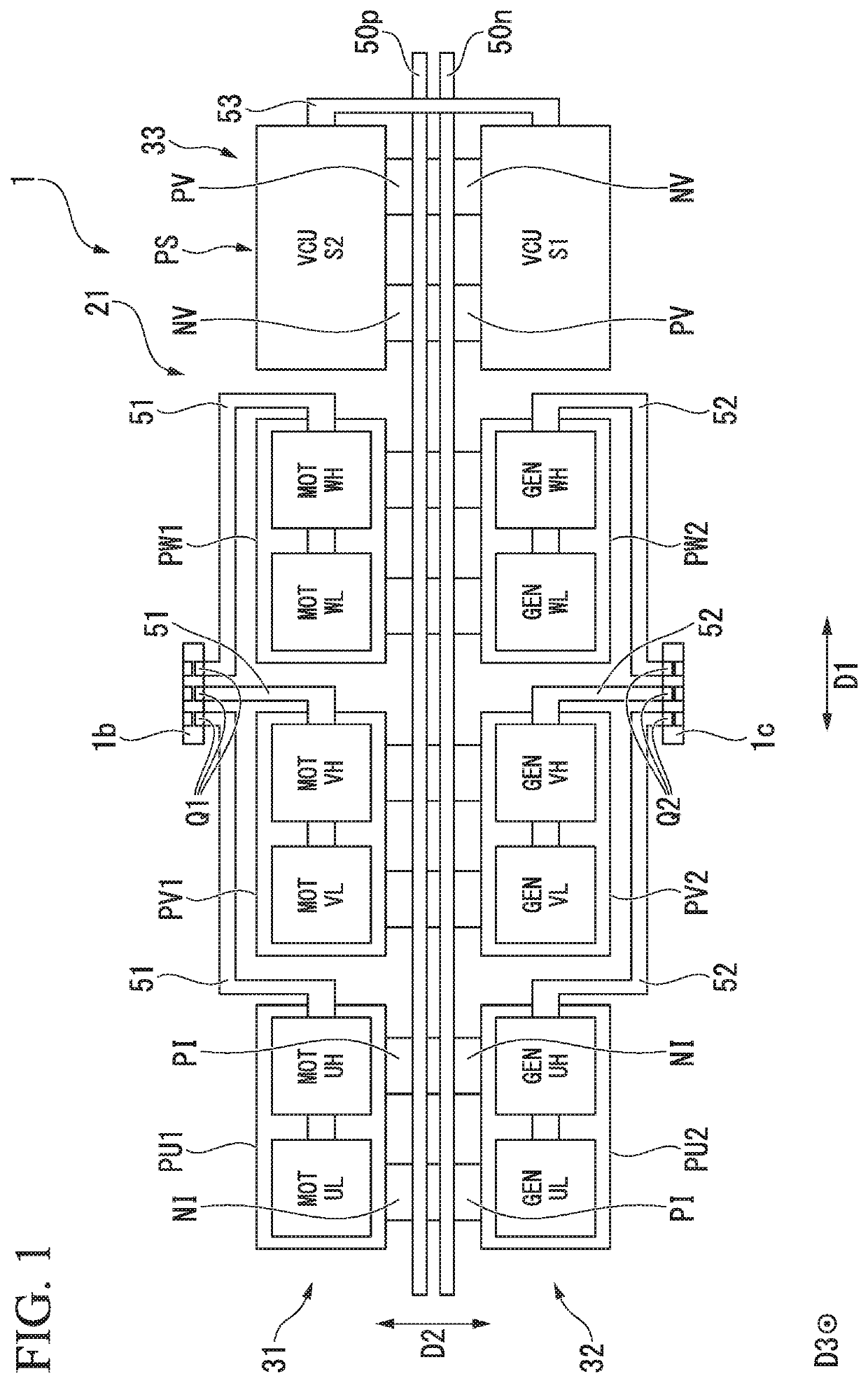
[0025]FIG. 1 is a plan view schematically illustrating a configuration of a power conversion device 1 according to an embodiment of the present invention.

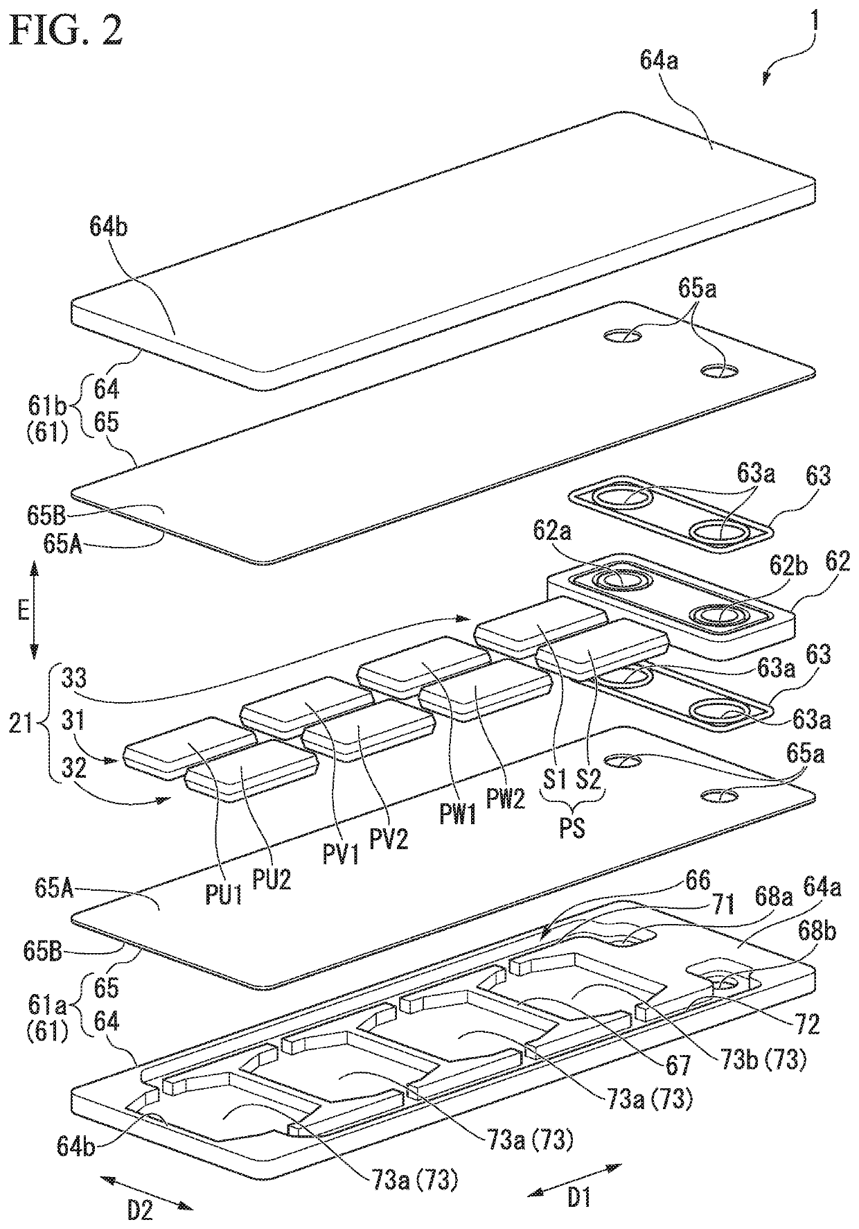
[0026]FIG. 2 is an exploded perspective view schematically illustrating a configuration of a power conversion device 1 ac...


PUM


Abstract

A refrigerant flow channel includes a first flow channel extending in a first direction and a plurality of first branching flow channels extending in a second direction by branching from the first flow channel. Three element arrays corresponding to a first motor for driving and three element arrays corresponding to a second motor for power generation are respectively disposed side by side in the first direction on a mounting surface. The element array of the first motor in each phase and the element array of the second motor in each phase face each other in the second direction, and are disposed at positions overlapping the first branching flow channel in a plan view. The element array of the first motor is located on an upstream side of the first branching flow channel with respect to the element array of the second motor.

Description

CROSS-REFERENCE TO RELATED APPLICATION[0001]Priority is claimed on Japanese Patent Application No. 2017-202664, filed Oct. 19, 2017, the content of which is incorporated herein by reference.BACKGROUND OF THE INVENTIONField of the Invention[0002]The present invention relates to a power conversion device.Description of Related Art[0003]Hitherto, as shown in FIG. 7, there has been known a semiconductor device 110 including a circuit element portion 101 constituted by a plurality of semiconductor elements, a circuit substrate 102 on which a plurality of circuit element portions 101 are mounted, and a cooler 103 which is connected to the circuit substrate 102 (see, for example, Japanese Unexamined Patent Application, First Publication No. 2015-079819). A refrigerant flow channel 111 is formed in the cooler 103 along a longitudinal direction (array direction of the circuit element portion 101). The circuit element portion 101 is cooled by heat exchange between a refrigerant flowing throug...

Claims


Application Information

Patent Timeline
Patent Type & Authority Patents(United States)
IPC IPC(8): H05K7/20H01L23/473
CPCH01L23/473H05K7/20927H05K7/20254H05K7/20872H01L23/46H02M7/53871H02P27/06
Inventor UNEME, TAKAHIRO
Owner HONDA MOTOR CO LTD
Why Eureka
Try Eureka