Cooling apparatus for a hot stamping die

a technology of cooling apparatus and hot stamping die, which is applied in lighting and heating apparatus, manufacturing tools, and shaping tools. it can solve the problems of dimensional defects, non-uniform low formability of high strength steels at room temperature, so as to achieve uniform high enthalpy of vaporization, and efficient cooling of hot stamping dies.

Active Publication Date: 2020-10-27
MYUNGSHIN IND CO LTD +2
View PDF8 Cites 0 Cited by
  • Summary
  • Abstract
  • Description
  • Claims
  • Application Information

AI Technical Summary

Benefits of technology

[0009]The present invention has been made in consideration of the aforementioned problem, and an object of the present invention is to provide a cooling apparatus for a hot stamping die, capable of more uniformly and efficiently cooling the hot stamping die.
[0011]The refrigerant flowing into or being supplied to the cooling channel of the hot stamping die may not be in the liquid-gas phase coexistence condition or its saturated liquid state. The temperature of the refrigerant supplied to the cooling channel may be slightly lower than the evaporating temperature or boiling point of the refrigerant, and desirably, be in the range of about 97% to about 99.5% of the evaporating temperature thereof. Such temperature condition allows the enthalpy of vaporization of the refrigerant, i.e., the latent heat of the refrigerant to be sufficiently used for cooling the hot stamping die even when the difference is small between the temperature of the refrigerant supplied to the hot stamping die and the temperature of the refrigerant discharged from the hot stamping die.
[0012]According to the present invention, the refrigerant may be in a two-phase coexistence region while passing through the cooling channel of the hot stamping die. If there is no environmental problem, the higher the enthalpy of vaporization of the refrigerant is more desirable.
[0013]According to the present invention, a compressor may not be necessary to compress the refrigerant discharged from the hot stamping die. The temperature change of the refrigerant circulating components of the cooling apparatus may be very small. The temperature of the refrigerant being discharged from the hot stamping die may be near the vaporization temperature of the refrigerant. For this, a flow rate of the refrigerant supplied to the hot stamping die may be controlled.
[0016]According to the cooling apparatus according to the present invention, since the hot stamping die is cooled using latent heat of a refrigerant, the temperature of the refrigerant may be constantly maintained in the cooling channel, which ensures uniform cooling of the hot stamping die.
[0017]According to the present invention, efficient cooling of the hot stamping die can be achieved by using a refrigerant having a high enthalpy of vaporization.

Problems solved by technology

Such high strength steels have low formability at room temperature and leads to dimensional defects due to spring back which constitute problems in forming process of high-strength steels.
This phenomenon causes non-uniform cooling of the hot stamping die and deteriorates the quality of the hot stamped body parts.

Method used


Image

  • Cooling apparatus for a hot stamping die
  • Cooling apparatus for a hot stamping die

Examples


Embodiment Construction

[0021]In order to help understand features of the present invention, a cooling apparatus for a hot stamping die according to embodiments of the preset invention will be described in more detail.

[0022]To help understanding of the embodiments to be described, it is to be noted that in giving reference numerals to elements of each drawing, like reference numerals refer to like elements even though like elements are shown in different drawings.

[0023]Further, in describing the present invention, well-known functions or constructions will not be described in detail since they may unnecessarily obscure the understanding of the present invention.

[0024]Hereinafter, the present invention will be described in detail through embodiments with reference to the accompanying drawings.

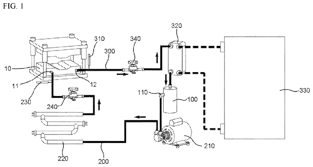
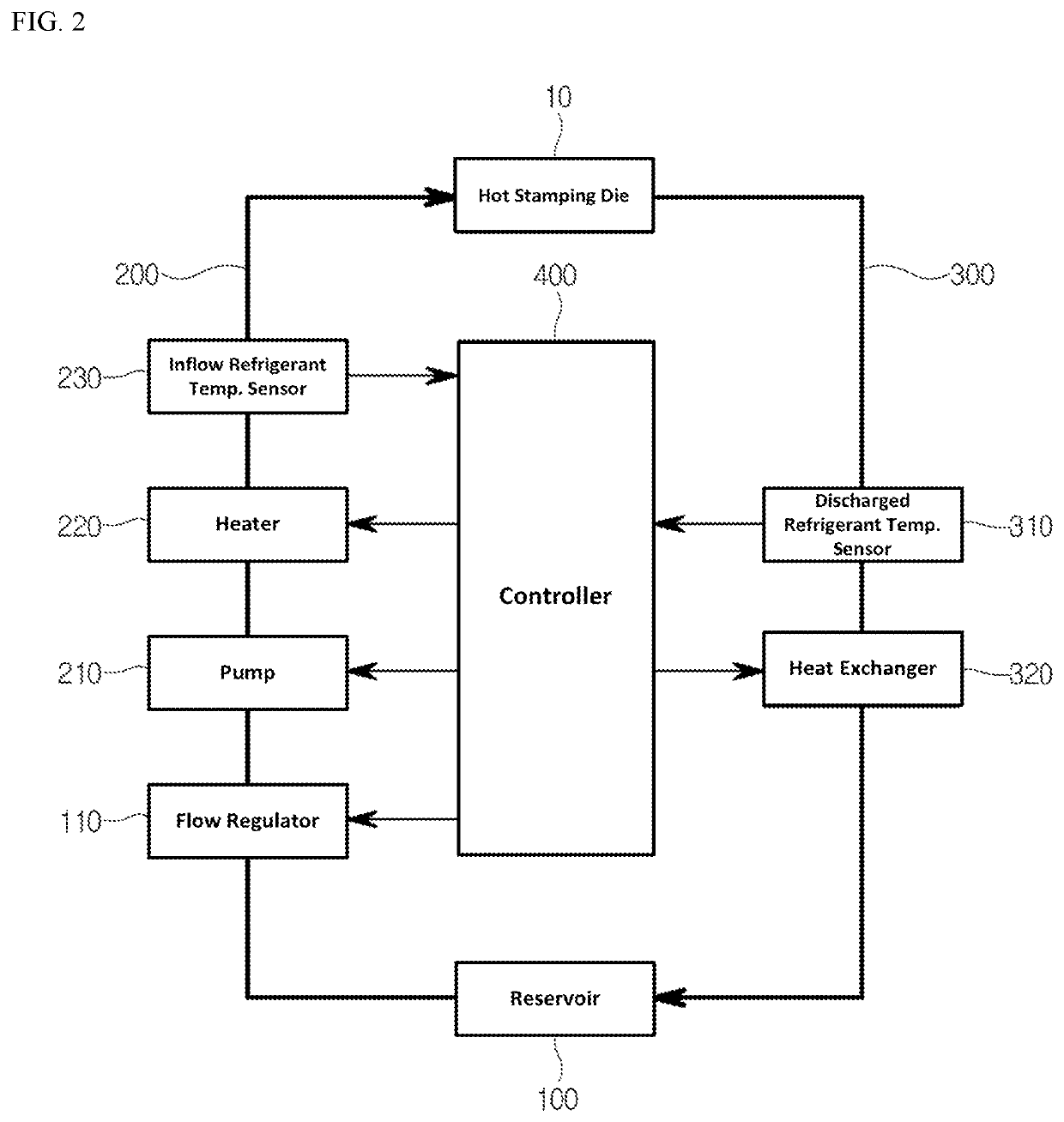
[0025]FIGS. 1 and 2 are respectively a schematic diagram and a schematic block diagram illustrating a cooling apparatus for a hot stamping die 10, according to an embodiment of the present invention.

[0026]Referring to ...


PUM

PropertyMeasurementUnit
temperatureaaaaaaaaaa
tensile strengthaaaaaaaaaa
temperatureaaaaaaaaaa

Abstract

A cooling apparatus for a hot stamping die is configured such that a refrigerant in a two-phase coexisting state of a liquid phase and a gas phase is supplied to a cooling channel formed in the hot stamping die to cool the hot stamping die using latent heat of the refrigerant. The refrigerant maintains a constant temperature in the cooling channel of the hot stamping die, which ensures uniform cooling of the hot stamping die.

Description

CROSS-REFERENCE TO RELATED APPLICATION[0001]This application claims the benefit of Korean Patent Application No. 10-2017-0046830, filed on Apr. 11, 2017, the disclosure of which is incorporated herein in its entirety by reference.BACKGROUND OF THE INVENTION[0002]The present invention relates to a cooling apparatus for a hot stamping die, and more particularly, to a cooling apparatus for a hot stamping die, capable of more uniformly and effectively cooling the hot stamping die.[0003]Generally, the proportion of vehicle body parts made of high strength steels increases to meet the environmental regulations and achieve vehicle weight reduction.[0004]Such high strength steels have low formability at room temperature and leads to dimensional defects due to spring back which constitute problems in forming process of high-strength steels.[0005]Recently, the number of hot stamped parts used in vehicles for the weight reduction is growing.[0006]In hot stamping process, a steel blank or sheet...

Claims


Application Information

Patent Timeline
Patent Type & Authority Patents(United States)
IPC IPC(8): B21D37/16B21D22/02
CPCB21D22/022B21D37/16F25B2700/21174F25B2700/21175F25B2600/21F25B2600/2515B21D37/10
Inventor PARK, SUNG YONGEOM, WON IKYUN, SUNG HOKWON, JUN HOKIM, YONG CHAN
Owner MYUNGSHIN IND CO LTD
Why Eureka
Try Eureka