Post-Crimping Inspection of Scaffolds Mounted on Scaffold Delivery Systems

Active Publication Date: 2014-07-10
ABBOTT CARDIOVASCULAR
View PDF19 Cites 4 Cited by
  • Summary
  • Abstract
  • Description
  • Claims
  • Application Information

AI Technical Summary

Benefits of technology

[0015]The crimper system of the invention addresses the need for collecting data relating to a crimping process and prior to placing a restraining sheath over the crimped scaffold by incorporating an automated scaffold handling system and camera-based inspection system capable of collecting critical information about the scaffold and balloon prior to placing a restraining sheath over the scaffold. Such critical information may include a crimped scaffold outer diameter, the average and standard deviation of the outer diameter along the length of the crimped scaffold, the location of the scaffold end rings relative to the catheter marker bands and thus relative to the balloon tapers, the uniformity of balloon folds (as a way of predicting the degree of uniform expansion that will occur when the scaffold is deployed), crack propagation or fracture present in scaffold struts, uniformity of the compressed rings and crown angles lengthwise over the scaffold, flipping or overlapping struts, etc.
[0016]According to one aspect of the automated system, scaffold position relative to markers is recorded and then compared to a specification. This scaffold location will be a variable measurement data and not just pass/fail attribute data, in some embodiments, so that one can understand the effect of a scaffold location on product performance and use this data to optimize a specification to maximize yields while not compromising product performance. Through this process there can be a significant increase in yields. In other embodiments the automated process can include a pass-fail criteria, e.g., the relative position of distal or proximal end of a scaffold relative to a marker band is measured from an image, and if that number is greater than a predetermined number the scaffold is rejected, otherwise the scaffold is accepted. A similar pass/fail criteria may be developed based on a measured outer diameter.
[0017]An additional advantage of the crimper system is that more accurate assessments may be made about crimping processing parameters since the entire crimping process involves no manual manipulation of a scaffold or balloon by technicians. Accordingly, more accurate statistics of an influence or contributing factor to variances or changes in scaffold strength, integrity, balloon folding, etc. resulting from a modification of a processing parameter can be made. This is expected to lead to less of a need to perform destructive testing, such as when a relatively minor change is made in a processing parameter.
[0018]According to another aspect of the disclosure, a scaffold mounting system includes a crimper head and a pair of stations, located on opposite sides of the crimper head, for positioning first and second scaffold and catheter assemblies and aligning the first and second scaffolds on their respective balloon catheters prior to crimping the scaffolds to the balloons. Th

Problems solved by technology

As such, there is no ability for a manual inspection of this type of crimp

Method used


Image

  • Post-Crimping Inspection of Scaffolds Mounted on Scaffold Delivery Systems
  • Post-Crimping Inspection of Scaffolds Mounted on Scaffold Delivery Systems
  • Post-Crimping Inspection of Scaffolds Mounted on Scaffold Delivery Systems

Examples


Example

[0059]Throughout this disclosure, the balloon expandable implant will be called a “scaffold”, whether the description is referring to an implant made in whole or part of a metal material or a bioresorbable or biodegradable polymeric material, such as PLLA, or a biodegradable metal. In some instances, the term “scaffold” may be used, which is specifically referring to a biodegradable or bioresorbable polymer implant. “Stent” refers to a non-biodegradable or non-bioresorbable implant, unless indicated otherwise.

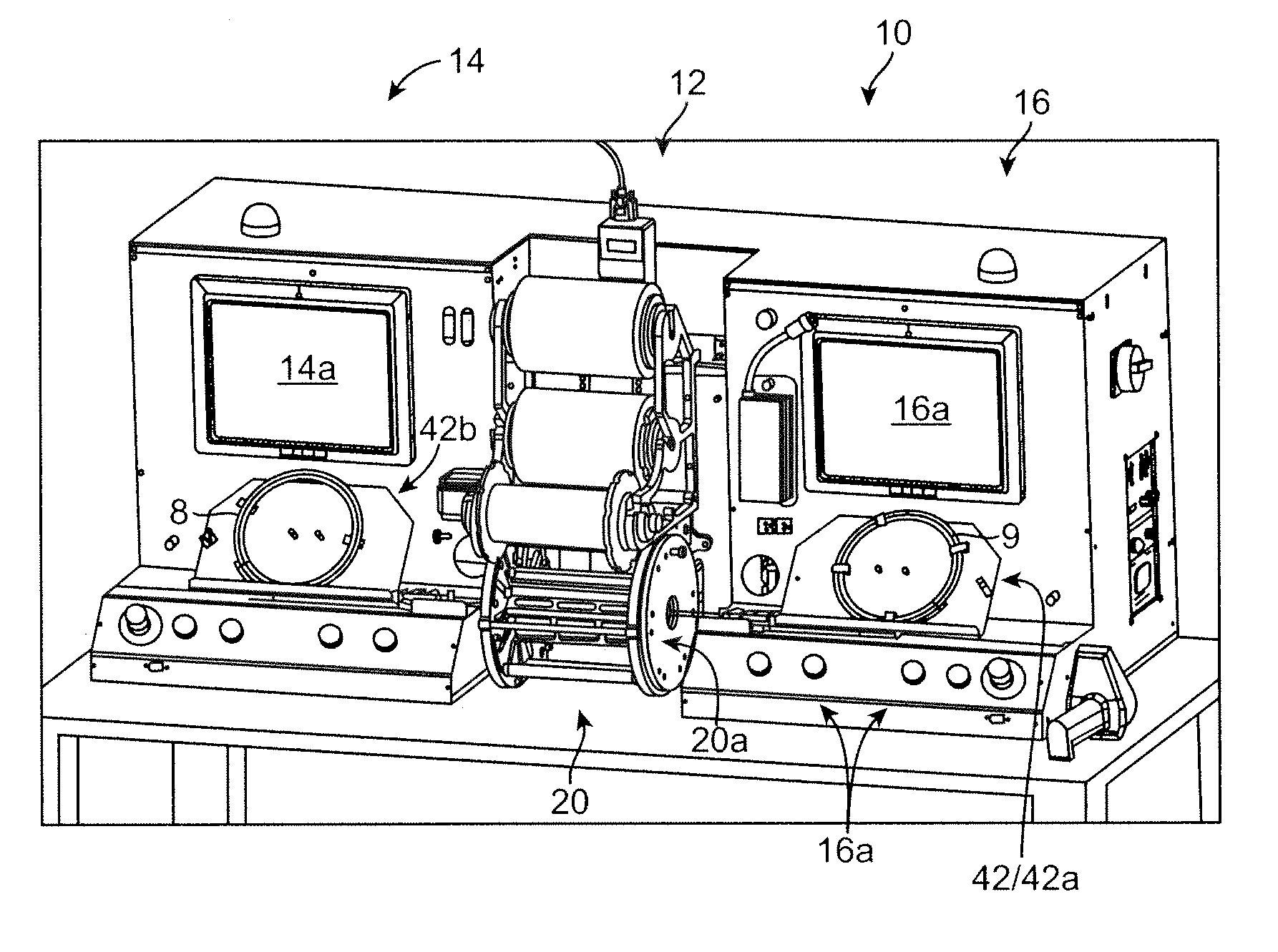
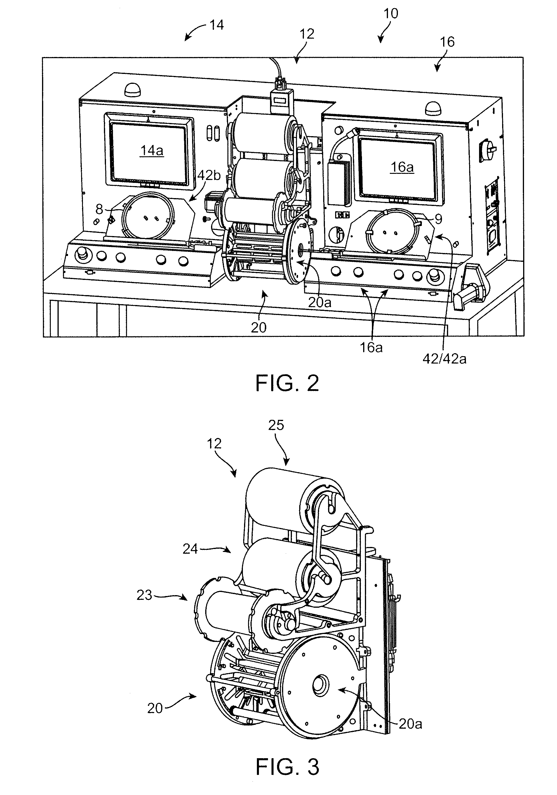
[0060]FIG. 2 illustrates a scaffold mounting system 10 according to one aspect of the disclosure. The scaffold mounting system 10 is configured for positioning a scaffold on a delivery balloon, then crimping the scaffold to the balloon in an automated fashion. The system 10 is preferably constructed so that two scaffolds may be simultaneously loaded onto separate balloon catheters, then each placed within a crimper head by a computer-controlled positioning and alignment system....


PUM

PropertyMeasurementUnit
Temperatureaaaaaaaaaa
Pressureaaaaaaaaaa
Diameteraaaaaaaaaa

Abstract

A system for mounting a scaffold on a balloon catheter includes two positioning and alignment stations, which are used to prepare a scaffold and catheter for crimping using the same crimping head. The system is configured for automated assembly of the scaffold and catheter prior to crimping and performing post-crimping inspection for the crimped scaffold and prior to placing a restraining sheath over the crimped scaffold.

Description

BACKGROUND OF THE INVENTION[0001]1. Field of the Invention[0002]The present invention relates to drug-eluting medical devices; more particularly, this invention relates to systems, apparatus and methods for mounting to a delivery balloon a balloon-expandable scaffold, such as a polymeric scaffold.[0003]2. Background of the Invention[0004]FIGS. 1A and 1B depict perspective views of a prior art crimping station used to crimp a balloon expandable scaffold to a deployment balloon of a balloon catheter. The crimping station includes a crimper head 220, an interactive screen 216 for programming a crimping sequence, e.g., diameter reduction, dwell times between successive crimps, temperature control of the crimper jaws, etc. A carriage 242 aligns a catheter 209 with the opening 222 to the crimper head 220 and advances the distal end 209b of the catheter, where a scaffold 100 and the balloon are located, into the crimper head 220. The crimper head 220 includes three rollers 223, 224 and 225...

Claims


Application Information

Patent Timeline
IPC IPC(8): B23P11/00
CPCB23P11/005A61F2/958A61F2002/9583A61F2/9522Y10T29/49769Y10T29/53022
Inventor VAN SCIVER, JASON
Owner ABBOTT CARDIOVASCULAR
Why Eureka
Try Eureka