Manipulator of robot and workpiece conveying robot using said manipulator

A technology of robots and manipulators, applied in the field of manipulators, can solve the problems of excessive cooling, easy distortion of manipulators, and inability to cool manipulators, and achieve the effects of efficient cooling, uniform cooling, and efficient and uniform cooling

Inactive Publication Date: 2010-05-12
SANKYO SEIKI MFG CO LTD
View PDF7 Cites 0 Cited by
  • Summary
  • Abstract
  • Description
  • Claims
  • Application Information

AI Technical Summary

Problems solved by technology

[0005] However, in the manipulator of the robot in Patent Document 1, the temperature of the cooling medium rises while the cooling medium circulates from the upstream portion of the pipe body to the downstream portion, and the manipulator at the downstream portion cannot be sufficiently cooled, and the manipulator at the upstream portion may not be sufficiently cooled. poor cooling condition
In addition, only the part in contact with the pipe body through which the cooling medium circulates is cooled, and there is a disadvantage that the entire robot arm cannot be sufficiently cooled.
[0006] That is, there is a problem of uneven cooling not only between the upstream and downstream parts of the cooling medium of the manipulator, but also between the part of the manipulator that is in contact with the pipe body and other parts
In addition, due to uneven cooling, there is also the problem that the manipulator itself is easy to twist and deform
[0007] In addition, in the manipulator of the robot of Patent Document 1, a pipe body made of metal with high thermal conductivity is extended around the manipulator formed by cutting a solid material, so the manipulator is relatively heavy, and there is a problem with the operation of the manipulator. Issues that adversely affect performance and productivity

Method used


Image

  • Manipulator of robot and workpiece conveying robot using said manipulator
  • Manipulator of robot and workpiece conveying robot using said manipulator
  • Manipulator of robot and workpiece conveying robot using said manipulator

Examples


Embodiment Construction

[0043] Next, preferred modes for carrying out the present invention will be described with reference to the drawings.

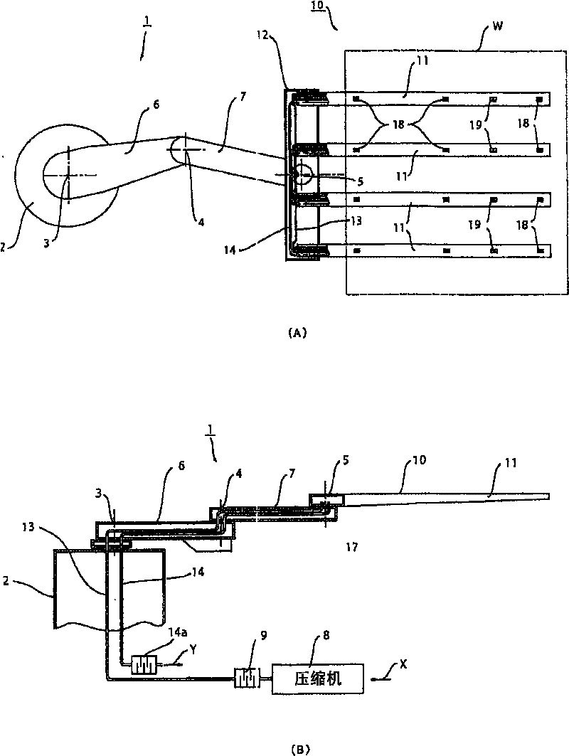
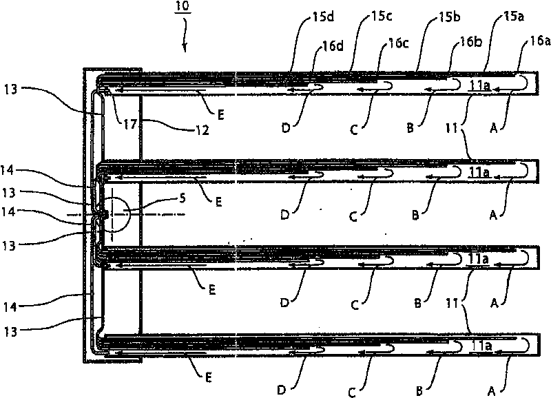
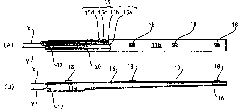
[0044] figure 1 Showing the schematic structure of the workpiece transfer robot of the embodiment of the present invention, figure 1 (A) is a plan view, figure 1 (B) is a side sectional view. The workpiece transfer robot 1 includes a transfer system for carrying a workpiece into and out of a heating furnace in a high-temperature environment, and a robot cooling system for cooling a robot arm. In addition, the workpiece transfer robot 1 of this embodiment is used in a manufacturing process of a flat panel display (FPD) requiring a certain degree of cleanliness, and is used to transfer a glass substrate W as a workpiece.

[0045] (Schematic structure of the conveying system)

[0046] First, the transfer system will be described. The workpiece transfer robot 1 (hereinafter simply referred to as "robot 1") includes: a first arm 6 that can rotate around the j...


PUM


Abstract

The present invention provides a manipulator capable of efficiently and uniformly cooling the manipulator when a workpiece such as a glass substrate processed in hot environment is carried, and havinglightweight structure in comparison with a conventional one, and a workpiece carrying robot using the manipulator. The manipulator of a robot of the present invention comprises a loadbearing part 11which is formed in a shape having a hollow 11a insulated from the outside and for placing the workpiece thereon, medium introducing pipes 15 for introducing a cooling medium into the hollow 11a on oneend side of the loadbearing part 11, and a medium discharge opening 17 for discharging the cooling medium from the hollow 11a on the other end side of the loadbearing part 11.

Description

technical field [0001] The present invention relates to a manipulator of a robot for processing workpieces such as glass substrates and wafers in a high-temperature environment, and a workpiece transfer robot using the manipulator. Background technique [0002] Conventionally, in the manufacturing process of flat panel displays (FPD) such as liquid crystal displays and plasma displays, and semiconductors, in order to transfer substrates such as flat glass and wafers as their base materials from a certain process to other processes as workpieces, many Sometimes use a substrate transfer robot. In addition, in this manufacturing process, the process of processing in a high-temperature heating furnace is included. For example, when manufacturing a glass substrate, the following steps are sometimes provided: taking out the glass substrate from the box for conveying between processes, coating the surface of the glass substrate with a chemical solution, and then carrying it into a...

Claims


Application Information

Patent Timeline
Patent Type & Authority Patents(China)
IPC IPC(8): B25J1/04B25J15/00
CPCB25J15/06B25J19/0054B65G49/061B65G61/00H01L21/677
Inventor 竹内靖典矢泽隆之
Owner SANKYO SEIKI MFG CO LTD
Why Eureka
Try Eureka