Hoop clamp for hoop assembly

A technology of clamp clamps and clamps, which is used in hand-held tools, manufacturing tools, workpiece clamping devices, etc. Effect

Inactive Publication Date: 2021-01-26
湖北超卓航空技术有限公司
View PDF8 Cites 0 Cited by
  • Summary
  • Abstract
  • Description
  • Claims
  • Application Information

AI Technical Summary

Problems solved by technology

[0006] In view of the above problems, the present invention designs a clamp clamp for clamp assembly, which facilitates the operator to remedy defective products, and at the same time solves the problem that a single clamp cannot be used universally

Method used


Image

  • Hoop clamp for hoop assembly
  • Hoop clamp for hoop assembly
  • Hoop clamp for hoop assembly

Examples


Embodiment 1

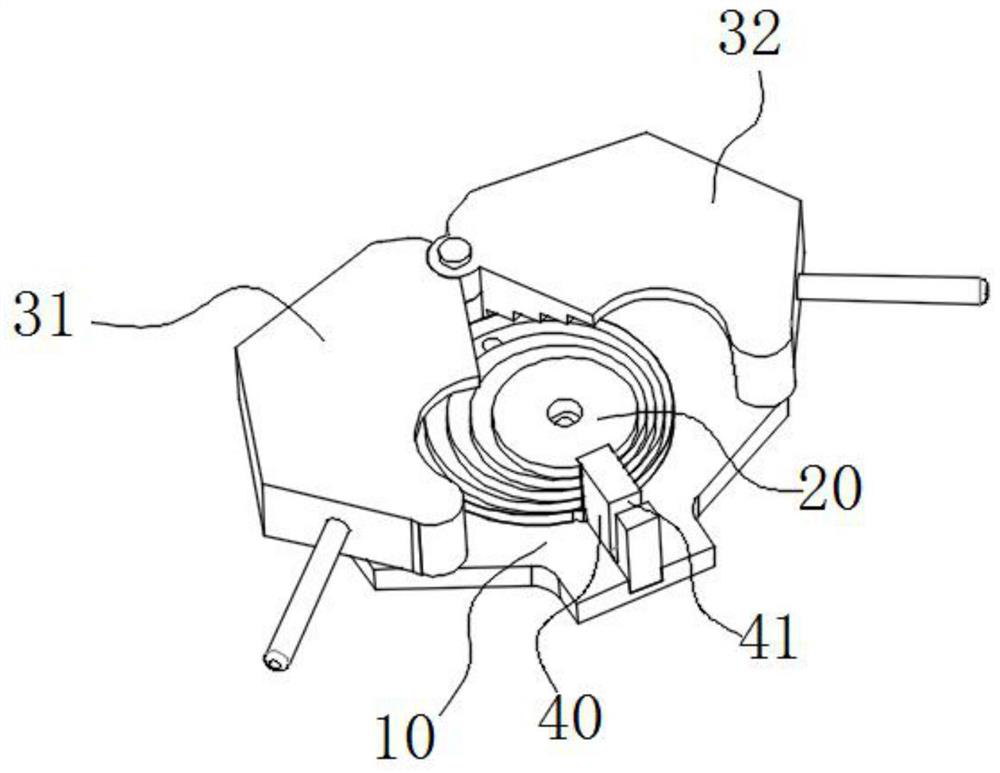
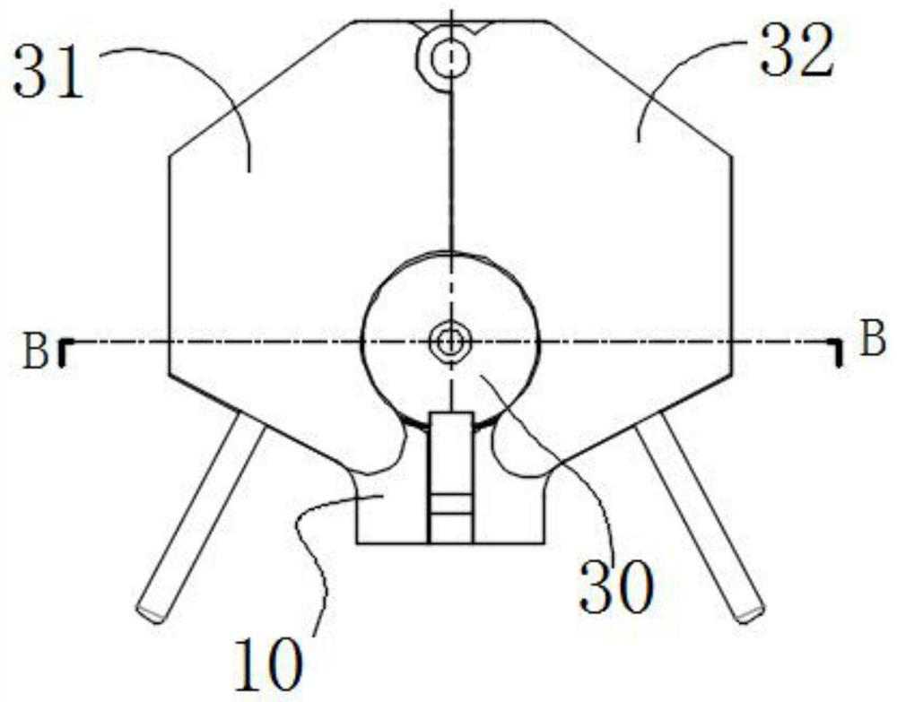
[0042] Embodiment 1: The first pliers body 31 and the second pliers body 32 are hinged to each other to form a hinge point, and the first pliers body 31 and the second pliers body 32 rotate relatively around the hinge point.

[0043] It can be understood that a rotating shaft is provided on the base plate 10, and rotating holes are respectively provided on the first pliers body 31 and the second pliers body 32, and the first pliers body 31 and the second pliers body 32 are both socketed through the rotating holes. On the rotating shaft, the hinge of the first pliers body 31 and the second pliers body 32 is realized; when the clamp band needs to be pressed together, the clamp band is first placed on the mold table, and then the first clamp body 31 and the second clamp body are rotated. The second pliers body 32 makes the two pliers bodies close to each other and slowly realizes the compression of the clamp band, so that the two ends of the clamp band are gradually approached.

Embodiment 2

[0044] Embodiment 2: The first pliers body 31 and the second pliers body 32 are arranged on the left and right sides of the core body 20 so that they can move linearly relative to each other, and driving parts are respectively arranged on the left and right sides of the core body 20 (not shown) to drive the first pliers 31 and the second pliers 32; under the action of the driver, the first pliers 31 on the left side of the core 20 move to the right, and the ones on the right side of the core 20 move to the right. The second pliers body 32 moves to the left, and the first pliers body 31 and the second pliers body 32 move relative to each other to realize the pressing of the band, so that the two ends of the band are close to each other.

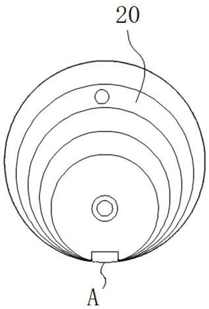
[0045] Optionally, an upwardly extending positioning block 40 is also provided on the base plate 10; a positioning notch 21 matching the positioning block is provided on the core 20 at a position directly opposite to point A; the core The body...


PUM


Abstract

The invention discloses a hoop clamp for hoop assembly, and relates to the field of aviation hoop manufacturing. The hoop clamp comprises a base plate, a core body, a first clamp body and a second clamp body; the core body is formed by stacking a plurality of molding tables which are of cylindrical structures and are different in diameter, the axis of each molding table is perpendicular to the base plate, and the axes of the molding tables are not collinear; projections of every two adjacent molding tables on the base plate are tangent to a point A; the first clamp body is provided with a first cavity; the second clamp body is provided with a second cavity; the first clamp body and the second clamp body are movably arranged on the base plate and located on the left side and the right sideof the core body respectively; and the first clamp body and the second clamp body relatively move, so that the first cavity and the second cavity are combined into a cavity matched with the core body.The hoop clamp is reasonable and simple in structure, the universality of the hoop clamp is realized by fusing the structures of different clamps, and great convenience is provided for an operator touse.

Description

technical field [0001] The invention relates to the field of aviation clamp manufacturing, in particular to a clamp clamp used for clamp assembly. Background technique [0002] Aviation clamps are an important part of the reinforcement of aircraft pipelines. They are used in air conditioning, oil circuits and other systems on aircraft. There are many pipelines on aircraft with different diameters. Therefore, in order to make the stable and fixed connection between various pipelines, the design There are also many specifications of clamp parts. [0003] The composition of the clamp generally includes a clamp band and a screw connecting the two ends of the clamp band. The clamp band is formed into a circular arc shape of a specified size on a punching machine using a bending die, and then the screw and the clamp band are assembled by an assembly machine. Assembly is performed so that the clamp is formed. [0004] In the actual application process, there are a small number of...

Claims


Application Information

Patent Timeline
IPC IPC(8): B25B27/14B25B11/02
CPCB25B27/14B25B11/02
Inventor 李羿含王亮李星彤卓东东高植强徐建
Owner 湖北超卓航空技术有限公司
Why Eureka
Try Eureka