
Ship and sail for ship

A technology for sails and ships, which is applied in ship propulsion, ship construction, ship parts, etc. It can solve the problems of small forward thrust, poor reliability of the turning mechanism, and the inability to mobilize the willingness and enthusiasm of users to install sails. Large sail area, simple control effect

Pending Publication Date: 2021-01-26
张娟
View PDF2 Cites 0 Cited by
  • Summary
  • Abstract
  • Description
  • Claims
  • Application Information

AI Technical Summary

Problems solved by technology

[0003] 1. The efficiency is low, the forward thrust generated by a single sail is small, and the energy saving effect is not obvious
[0004] 2. The mechanism is complex and the failure rate is high, resulting in high daily maintenance costs
[0005] 3. The mast is generally used as the stressed part (called cantilever beam structure in material mechanics), and the bearing capacity is poor
[0006] 4. Due to changes in wind direction, the blade angle must be adjusted in real time and frequently, and corresponding mechanical transmission devices or control mechanisms must be configured at the same time
[0007] 5. R&D costs and manufacturing costs are high, resulting in low return on investment for users, and the willingness and enthusiasm of users to install sails cannot be well mobilized, which restricts the promotion and application of new technologies in actual production
After the motor starts, it is difficult to control the blade to stop at the desired angle
[0017] When one of the blades fails, such as the retracting action or the flipping action is stuck, it will affect all the blades and cannot move
The reliability of the hand-operated retractable mechanism and the flip mechanism of the chain drive is very poor, and it is impossible to guarantee retractable and flip operations anytime and anywhere
The failure rate of this control method will be very high, and the main failure points are wire ropes, chains, pulleys, etc., and the actual operation and maintenance workload of the crew will be relatively large.

Method used


Image

  • Ship and sail for ship
  • Ship and sail for ship
  • Ship and sail for ship

Examples


Embodiment Construction

[0064] The following will clearly and completely describe the technical solutions in the embodiments of the present invention with reference to the accompanying drawings in the embodiments of the present invention. Obviously, the described embodiments are only some, not all, embodiments of the present invention. The following description of at least one exemplary embodiment is merely illustrative in nature and in no way taken as limiting the invention, its application or uses. Based on the embodiments of the present invention, all other embodiments obtained by persons of ordinary skill in the art without creative efforts fall within the protection scope of the present invention. The relative arrangements, expressions and numerical values ​​of components and steps set forth in these embodiments do not limit the scope of the present invention unless specifically stated otherwise. At the same time, it should be understood that, for the convenience of description, the sizes of the...


PUM


Abstract

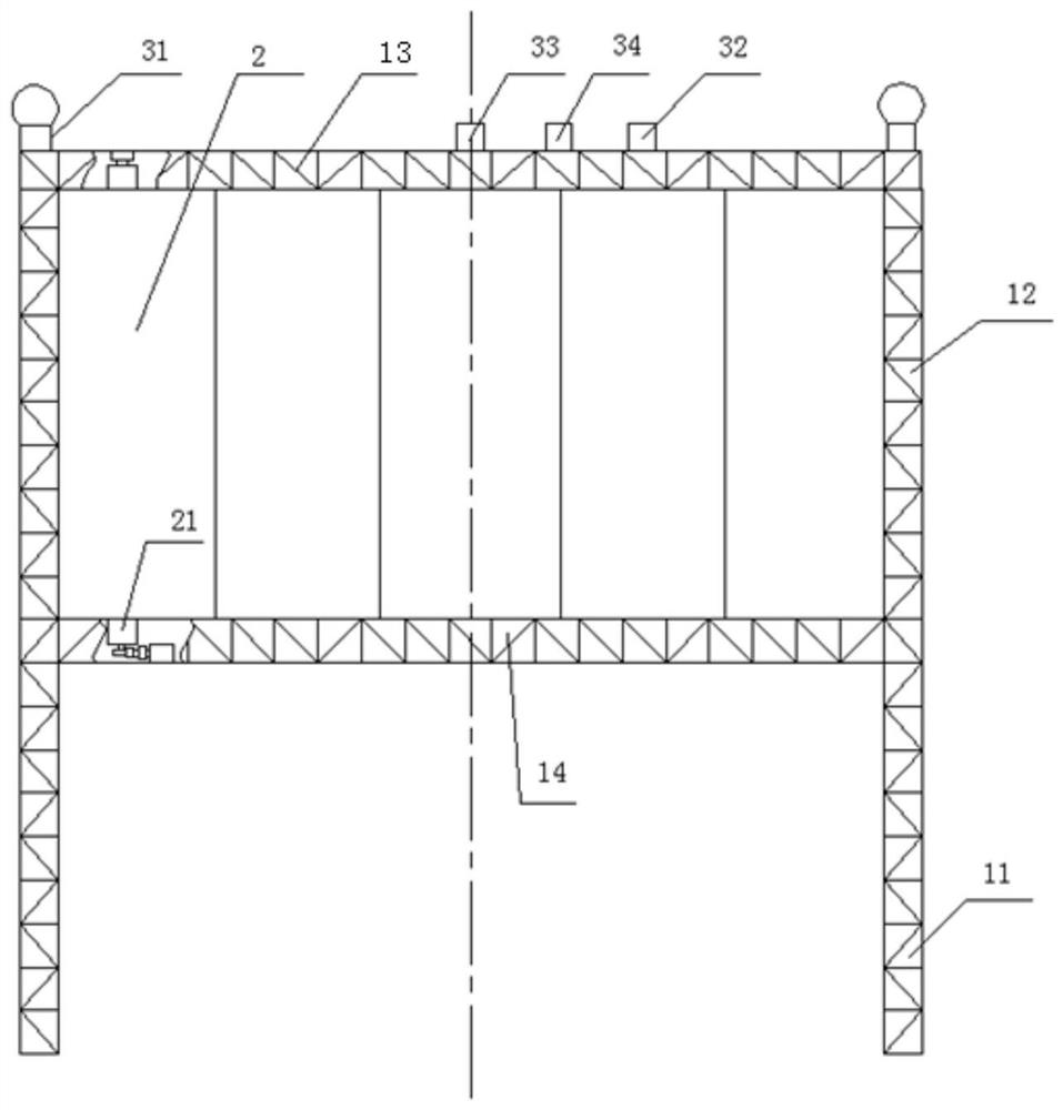
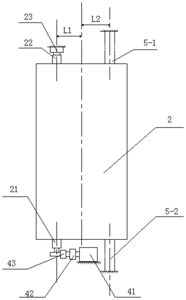
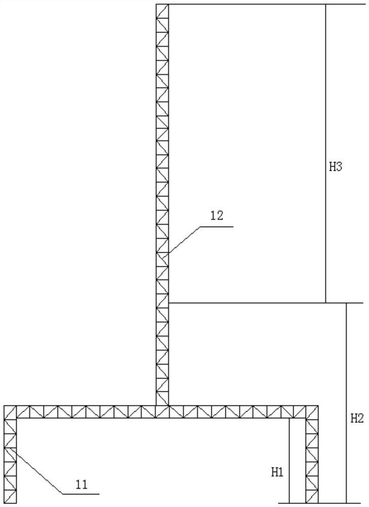
The invention discloses a ship and a sail for the ship. The sail for the ship comprises two supporting legs and a louvered sail body supported by the two supporting legs. The louvered sail body comprises an upper cross beam, a lower cross beam, a plurality of sail blades arranged longitudinally and a plurality of electromagnetic limiting stop pins. Each sail blade comprises a blade body, and an eccentric shaft is arranged at the position, away from L1, of one side of the longitudinal axial symmetric line of each blade body. The two eccentric shafts are respectively an upper eccentric shaft anda lower eccentric shaft which are coaxially arranged; in the two eccentric shafts, one eccentric shaft is connected with the power output end of a driving device, and the other eccentric shaft is provided with an angle sensor; for each sail blade, at least one electromagnetic limiting stop pin is mounted on the upper cross beam and the lower cross beam respectively. The ship and the sail for theship are simple and reliable in overall structure, high in wind energy absorbing efficiency, greatly reduced in manufacturing cost and simple in daily maintenance.

Description

technical field [0001] The invention relates to a ship and a ship sail. Background technique [0002] The current sail products in the international and domestic markets are technically positive and progressive, but at the same time there are various deficiencies, and the common problems are: [0003] 1. The efficiency is low, the forward thrust generated by a single sail is small, and the energy saving effect is not obvious [0004] 2. The mechanism is complex and the failure rate is high, resulting in high daily maintenance costs. [0005] 3. The mast is generally used as the stressed part (called cantilever beam structure in material mechanics), and its bearing capacity is poor. [0006] 4. Due to changes in wind direction, the blade angle must be adjusted in real time and frequently, and corresponding mechanical transmission devices or control mechanisms must be configured. [0007] 5. R&D costs and manufacturing costs are high, resulting in low return on investment f...

Claims


Application Information

Patent Timeline
Patent Type & Authority Applications(China)
IPC IPC(8): B63H9/06B63H9/067B63H9/065
CPCB63H9/06B63H9/067B63H9/065Y02T70/5236
Inventor 王昱然
Owner 张娟
Learn More