Eureka AIR delivers breakthrough ideas for toughest innovation challenges, trusted by R&D personnel around the world.

An automatic infusion bottle changing device

An automatic, bottle holder technology, applied in the field of medical devices, can solve the problems of slow bottle changing, mutual interference, and high equipment cost, and achieve the effect of fast bottle changing, ensuring work, and reducing production costs.

Active Publication Date: 2022-07-01
YANTAI NANSHAN UNIV
View PDF16 Cites 0 Cited by
  • Summary
  • Abstract
  • Description
  • Claims
  • Application Information

AI Technical Summary

Problems solved by technology

[0002] my country is a country with a large population, and the development of medical care is an important guarantee for the development of a country. However, most of the traditional infusion methods use manual bottle changing. The process of changing bottles is simple and highly repeatable.
[0003] The Chinese utility model patent with the application number 201620901644.2 discloses an automatic infusion needle changing device for medical care, which drives the needle up and down through a needle motor, and realizes the rotation of the infusion bottle through a stepping motor to realize automatic bottle change. Driven by two motors, there are the following problems: 1) The bottle change action is realized by two motors. In order to avoid the mutual interference of the two motors, after the conveying bottle is rotated in place, it needs to wait for a certain period of time before the needle can move, and the bottle change is completed. , resulting in slow bottle change; 2) The stepping motor drives the infusion bottle to rotate. Due to the heavy weight and high inertia of the infusion bottle, it is difficult to stop the infusion bottle immediately when the infusion bottle is delivered, which makes it difficult to align the needle with the infusion bottle. The work is very unstable; 3) In order to realize the precise control of the needle and the infusion bottle, two servo motors or stepping motors are required, resulting in high equipment costs

Method used


Image

  • An automatic infusion bottle changing device
  • An automatic infusion bottle changing device
  • An automatic infusion bottle changing device

Examples


Embodiment Construction

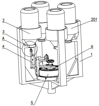
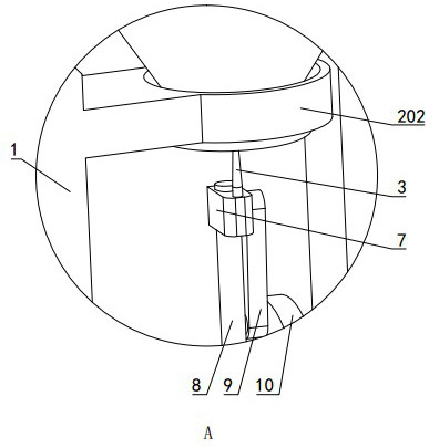
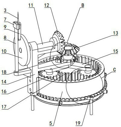
[0021] Figures 1~5 is the best embodiment of the present invention, the following is combined with the appendix Figures 1~5 The present invention will be further described.

[0022] An infusion automatic bottle changing device includes an infusion bottle holder 2 and a puncture needle 3 arranged on the lower side of the infusion bottle holder 2, and also includes a planetary gear train 6, a mounting frame 14 and a power device, and the mounting frame 14 is mounted on the planetary gear train 6. The puncture needle 3 is mounted on the mounting frame 14 in a lifting and lowering manner, and the puncture needle 3 is connected to the planetary carrier 15 of the planetary gear train 6 through the transmission mechanism, and moves with the planetary gear 5. The frame 15 rotates to move up and down, a lift lock mechanism 18 is arranged between the transmission mechanism and the planet carrier 15, a rotation lock mechanism 19 is connected to the ring gear 5, and the power unit is c...


PUM


Abstract

An infusion automatic bottle changing device belongs to the technical field of medical devices. The mounting bracket (14) is installed on the side of the inner gear (5) of the planetary gear train (6), and moves synchronously with the inner gear (5), and the puncture needle (3) can be mounted on the mounting bracket (14) in a liftable manner , the puncture needle (3) is connected with the planet carrier (15) of the planetary gear train (6) through the transmission mechanism, and rises and falls with the rotation of the planetary carrier (15). A lift lock is provided between the transmission mechanism and the planetary carrier (15). There is a locking mechanism (18), the inner gear (5) is connected with a rotation locking mechanism (19), and the power device is connected with the sun gear (17) and drives it to rotate. The automatic infusion bottle changing device has fast bottle changing speed, convenient and precise control of the position of the puncture needle, can ensure the alignment of the puncture needle and the infusion bottle, and ensure stable operation of the equipment.

Description

technical field [0001] An infusion automatic bottle changing device belongs to the technical field of medical devices. Background technique [0002] my country is a country with a large population, and the development of medical care is an important guarantee for the development of a country. However, most of the traditional infusion methods still use manual bottle changing, and the bottle changing process is simple and repeatable. [0003] The Chinese utility model patent with application number 201620901644.2 discloses an automatic infusion needle exchange device for medical care, which drives the needle stick up and down through the needle stick motor, and realizes the rotation of the infusion bottle through the stepping motor to realize the automatic bottle exchange, but it uses two Driven by two motors, there are the following problems: 1) The bottle changing action is realized by two motors. In order to avoid the problem of mutual interference between the two motors, a...

Claims


Application Information

Patent Timeline
Patent Type & Authority Patents(China)
IPC IPC(8): A61M5/14A61M5/168
CPCA61M5/1407A61M5/16827A61M5/16845
Inventor 王艳娟胡晓青张彦芝邹慧永张倩杨春苗王鑫培张金道李钺晖李强曲俊刚
Owner YANTAI NANSHAN UNIV
Why Eureka
Eureka Blog
Learn More