Optical machine equipment with optical machine power supply convenient to replace

A technology of optical mechanics and power supply, applied in optics, instruments, projection devices, etc., can solve problems such as inability to achieve fixation, inability to reduce the work intensity of staff, troublesome replacement of optical and mechanical equipment, etc.

Inactive Publication Date: 2021-01-26
浙江德航智能科技有限公司
View PDF4 Cites 0 Cited by
  • Summary
  • Abstract
  • Description
  • Claims
  • Application Information

AI Technical Summary

Problems solved by technology

[0002] In today's society, there are many fields and occasions where optical and mechanical equipment is used, such as in the fields of monitoring and command, and the large screens used in these fields need to work uninterrupted, so the internal The display electronic components produce a large load and consumption. For example, the power supply in the optical-mechanical equipment needs to be replaced regularly. The existing optical-mechanical equipment usually installs its power supply on the inner side of the optical-mechanical housing. When the power supply needs to be replaced, Usually it is necessary to remove the entire optical-mechanical device from the display unit, then disassemble the optical-mechanical case, replace the power supply, and then put the optical-mechanical device back into the display unit. However, due to the movement of the optical-mechanical device position, the display unit may display The out-of-screen image deviates from the surrounding frontal image, which visually causes discomfort to the viewer
[0003] In the existing technology, for example, the opto-mechanical equipment proposed in Patent No. CN108563086A is convenient for replacing the opto-mechanical power supply. Since the fixing of the opto-mechanical equipment and the opening of the mounting frame are all done manually, And in the process of fixing the optomechanical device, it did not take into account the longitudinal fixation of the optomechanical device, which may cause the optomechanical device to be displaced again during the deflection process with the base plate, so that it can be displayed on the display. The image displayed in the unit still has deviations, which cannot realize its fixing function, and cannot reduce the work intensity of the staff, but will cause unnecessary trouble for the replacement of optical and mechanical equipment

Method used


Image

  • Optical machine equipment with optical machine power supply convenient to replace
  • Optical machine equipment with optical machine power supply convenient to replace
  • Optical machine equipment with optical machine power supply convenient to replace

Examples


Embodiment

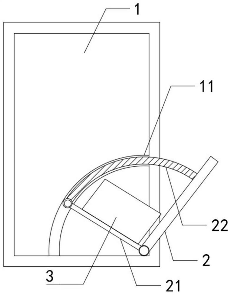
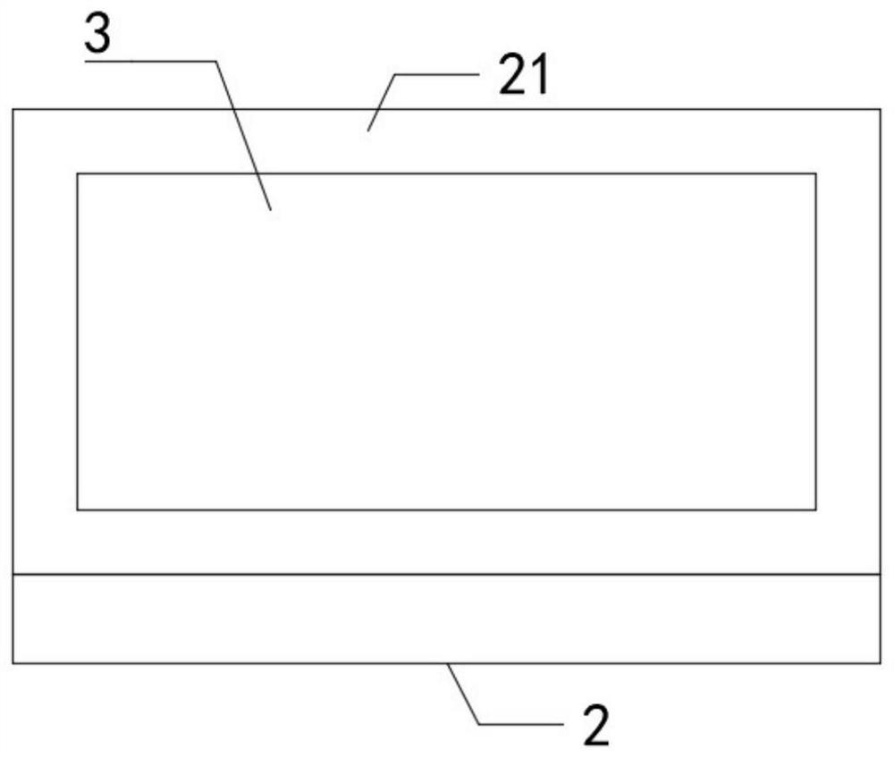
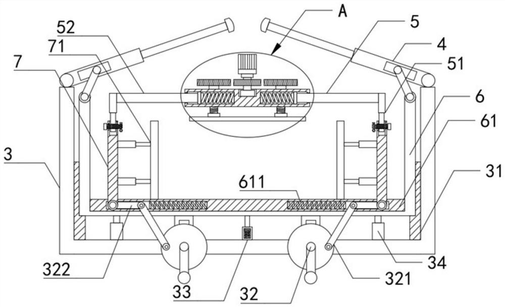
[0026] Such as Figure 1-5 As shown, an optomechanical device for easy replacement of the optomechanical power supply includes a device housing 1, a mounting frame 3 is slidably connected to the inner wall of the device housing 1, and an upper shutter 4 is rotatably connected to the upper end of the mounting bracket 3, and the upper shutter 4 A chute is provided on the side of the ground, and the inside of the chute is slidably connected with a straight rod. The upper end is fixedly connected with a fixed frame 5, the left and right sides of the support frame 6 are slidably connected to the left and right inner walls of the mounting frame 3, the inner wall of the device shell 1 is slidably connected to a bottom plate 21, and the mounting frame 3 is fixedly connected to the upper end of the bottom plate 21 On the surface.

[0027] Specifically, the inside of the device housing 1 is fixedly connected with the first slide rail 11, the structure of the first slide rail 11 is an a...


PUM


Abstract

The invention belongs to the field of optical machine equipment, and particularly relates to optical machine equipment with an optical machine power supply convenient to replace. The equipment comprises a device shell, wherein a mounting frame is slidably connected to the inner wall of the device shell, an upper shielding plate is rotatably connected to the upper end of the mounting frame, a supporting frame is fixedly connected to the interior of the mounting frame, a fixing frame is fixedly connected to the upper end of the supporting frame, the left side and the right side of the supportingframe are slidably connected to the inner walls of the left side and the right side of the mounting frame, a bottom plate is slidably connected to the inner wall of the device shell, and the mountingframe is fixedly connected to the surface of the upper end of the bottom plate. According to the invention, a sliding plate is driven by a rotary disc, a long connecting rod and a short connecting rod to rotate towards the inner side so as to achieve the transverse fixing of optical machine equipment, a driving gear is driven by a motor to indirectly drive a threaded rod to move towards the lowerside so as to achieve the longitudinal fixing of the optical machine equipment, and when an air cylinder drives a supporting frame to ascend, an upper shielding plate at the upper end of a mounting frame can be opened at the same time.

Description

technical field [0001] The invention belongs to the field of optical-mechanical equipment, and in particular relates to an optical-mechanical equipment for easy replacement of an optical-mechanical power supply. Background technique [0002] In today's society, there are many fields and occasions where optical and mechanical equipment is used, such as in the fields of monitoring and command, and the large screens used in these fields need to work uninterrupted, so the internal The display electronic components produce a large load and consumption. For example, the power supply in the optical-mechanical equipment needs to be replaced regularly. The existing optical-mechanical equipment usually installs its power supply on the inner side of the optical-mechanical housing. When the power supply needs to be replaced, Usually it is necessary to remove the entire optical-mechanical device from the display unit, then disassemble the optical-mechanical case, replace the power supply...

Claims


Application Information

Patent Timeline
Patent Type & Authority Applications(China)
IPC IPC(8): G03B21/54G03B21/14
CPCG03B21/145G03B21/54
Inventor 杨明来傅冬群
Owner 浙江德航智能科技有限公司
Why Eureka
Try Eureka