Efficient heat dissipation and cooling power distribution cabinet

A power distribution cabinet, high-efficiency technology, applied in substation/power distribution device casing, electrical components, substation/switch layout details, etc., can solve problems such as low work efficiency, inconvenient maintenance, time-consuming and labor-intensive, etc., to improve work efficiency, The effect of easy maintenance

Inactive Publication Date: 2021-01-26
黄国兴
View PDF0 Cites 7 Cited by
  • Summary
  • Abstract
  • Description
  • Claims
  • Application Information

AI Technical Summary

Problems solved by technology

[0005] The purpose of the present invention is to provide a power distribution cabinet with high-efficiency heat dissipation and cooling, so as to solve the problem mentioned in the background art that when the electrical components of the existing power distribution cabinet break down and need to be repaired, the maintenance workers need to put their hands or even the whole body deep into the narrow space. It is inconvenient to repair in the power distribution cabinet. During the maintenance process, the maintenance workers need to use a screwdriver to remove the faulty electrical components for inspection. Laborious and low work efficiency
[0007] When working, when the electrical components of the existing power distribution cabinet break down and need to be repaired, the maintenance workers need to put their hands or even the whole body deep into the power distribution cabinet with a narrow space to repair, which is inconvenient to repair. Remove the faulty electrical components for inspection, and then use a screwdriver to reinstall the electrical components into the power distribution cabinet after the repair is completed, which is time-consuming and laborious, and the work efficiency is low. This device opens the cabinet door of the power distribution cabinet by the maintenance worker through the 
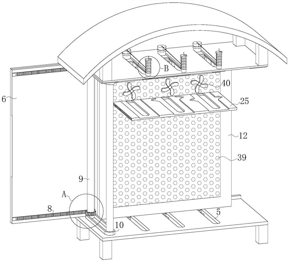
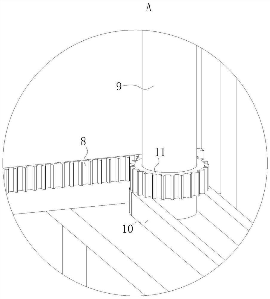
handle. At the same time, the racks fixedly connected at the upper and lower ends of the inner side of the cabinet door drive the transmission roller to rotate through the meshing gears, and the conveyor belt connected to the top and bottom of the transmission roller will move with the movement, and the mounting plate fixedly connected to the left side of the two conveyor belts will move. With the movement of the 
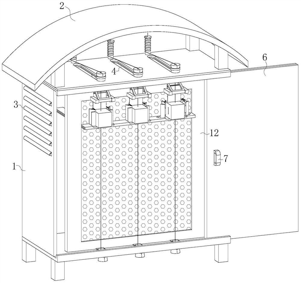
conveyor belt, it moves toward the cabinet door. When the mounting plate moves to the position of the pressing block, the damping mechanism on both sides of the supporting plate will damp the mounting plate, and the electrical components installed on the mounting plate will be just on the supporting plate. In the open gap position of the irregular chute, the lower end of the pressing block will first contact the top surface of the hollow plate. As the mounting plate continues to move forward, the pressing block will press the hollow plate downward, and the pressing plate fixedly connected As the hollow plate moves downward, the top of the T-shaped plate will slide on the lower surface of the pressure plate to the side away from the mounting plate, and the lower end of the T-shaped plate will slide outwards in the rectangular chute on the inside of the clamping plate, and the two sides of the electrical components The clamping plate will be opened to both sides under the action of the T-shaped plate, and the clamping blocks fixedly connected at the end of the clamping plate will move out of the clamping grooves on both sides of the electrical components. At this time, the maintenance workers only need to After the circuit on the electrical component is disassembled, the electrical component can be directly removed from the mounting plate. When the mounting plate continues to move forward, the hollow plate will be separated from the pressure block, and the hollow plate will return to its original position under the action of the torsion spring. The T-shaped plate Under the action of the clamping plate and the spring, it will be reattached to the mounting plate, and the clamping plate will re-clamp the electrical components. When the mounting plate moves to the position of each pressing block, the corresponding electrical components will be loosened. , the maintenance worker can choose to loosen the electrical components that need to be repaired by controlling the position of the open cabinet door. After loosening, the electrical components that need to be repaired can be removed directly. It is no longer necessary for the maintenance workers to use a screwdriver to disassemble the electrical components, saving time It saves labor and improves work efficiency, and the movement of the installation plate towards the cabinet door prevents maintenance workers from penetrating into the power distribution cabinet with narrow space during maintenance, making maintenance more convenient

Method used


Image

  • Efficient heat dissipation and cooling power distribution cabinet
  • Efficient heat dissipation and cooling power distribution cabinet
  • Efficient heat dissipation and cooling power distribution cabinet

Examples


Embodiment Construction

[0034] The following will clearly and completely describe the technical solutions in the embodiments of the present invention with reference to the accompanying drawings in the embodiments of the present invention. Obviously, the described embodiments are only some, not all, embodiments of the present invention. Based on the embodiments of the present invention, all other embodiments obtained by persons of ordinary skill in the art without creative efforts fall within the protection scope of the present invention.

[0035] see Figure 1-15 , the present invention provides a technical solution: a high-efficiency heat dissipation and cooling power distribution cabinet, including a cabinet body 1, an arc-shaped protective roof 2 is provided on the top of the cabinet body 1, heat dissipation windows 3 are provided on both sides of the cabinet body 1, and the cabinet body 1 The top and the bottom are respectively provided with inlet holes 4 and outlet holes 5, the front end of the ...


PUM


Abstract

The invention discloses an efficient heat dissipation and cooling power distribution cabinet in the technical field of power distribution cabinets, and the cabinet comprises a cabinet body, the top ofthe cabinet body is provided with an arc-shaped protection top, two sides of the cabinet body are provided with heat dissipation windows, and the top and bottom of the cabinet body are respectively provided with a wire inlet hole and a wire outlet hole. By arranging the mounting plate, the clamping plates, the T-shaped plate, the hollow plate, the pressing plate and the pressing block, a maintenance worker opens the cabinet door to enable the mounting plate to move outwards, when the mounting plate moves to different positions, the clamping plates on the two sides of different electrical components can be opened, the maintenance worker can directly take down the electrical components only at specific positions, maintenance workers do not need to use screwdrivers to disassemble electricalcomponents any more, time and labor are saved, the working efficiency is improved, the installation plate moves towards the cabinet door, the maintenance workers are prevented from going deep into thepower distribution cabinet with narrow space during maintenance, and maintenance is more convenient.

Description

technical field [0001] The invention relates to the field of power distribution cabinets, in particular to a high-efficiency heat dissipation and cooling power distribution cabinet. Background technique [0002] Power distribution cabinets are divided into power distribution cabinets, lighting distribution cabinets, and metering cabinets. They are the final equipment of the power distribution system. Power distribution cabinets are collectively referred to as motor control centers. , The motor control center is used in the occasions where the load is concentrated and there are many circuits. They distribute the electric energy of a certain circuit of the upper-level power distribution equipment to the nearby load. This level of equipment should provide protection, monitoring and control for the load. [0003] When the existing power distribution cabinet fails and needs to be repaired, the maintenance worker needs to put his hands or even the whole body deep into the power di...

Claims


Application Information

Patent Timeline
Patent Type & Authority Applications(China)
IPC IPC(8): H02B1/32H02B1/30H02B1/56
CPCH02B1/305H02B1/32H02B1/565
Inventor 黄国兴
Owner 黄国兴
Why Eureka
Try Eureka