A high voltage transmission line deicer

A high-voltage transmission line and deicer technology, applied in the mechanical field, can solve problems such as easy card grouping and large resistance

Active Publication Date: 2022-01-18
GUIZHOU POWER GRID CO LTD
View PDF16 Cites 0 Cited by
  • Summary
  • Abstract
  • Description
  • Claims
  • Application Information

AI Technical Summary

Problems solved by technology

[0007] In view of this, the object of the present invention is to provide a high-voltage transmission line deicer, which uses knocking instead of scraping, and solves the problem of excessive resistance and easy jamming of existing mechanical deicers

Method used


Image

  • A high voltage transmission line deicer
  • A high voltage transmission line deicer

Examples


Embodiment Construction

[0023] Hereinafter, preferred embodiments of the present invention will be described in detail with reference to the accompanying drawings. It should be understood that the preferred embodiments are only for illustrating the present invention, but not for limiting the protection scope of the present invention.

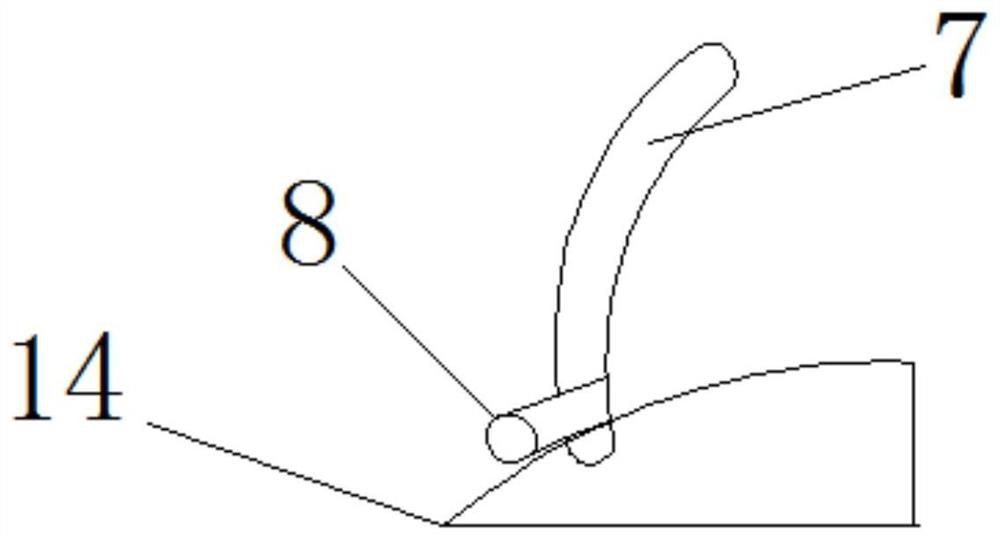
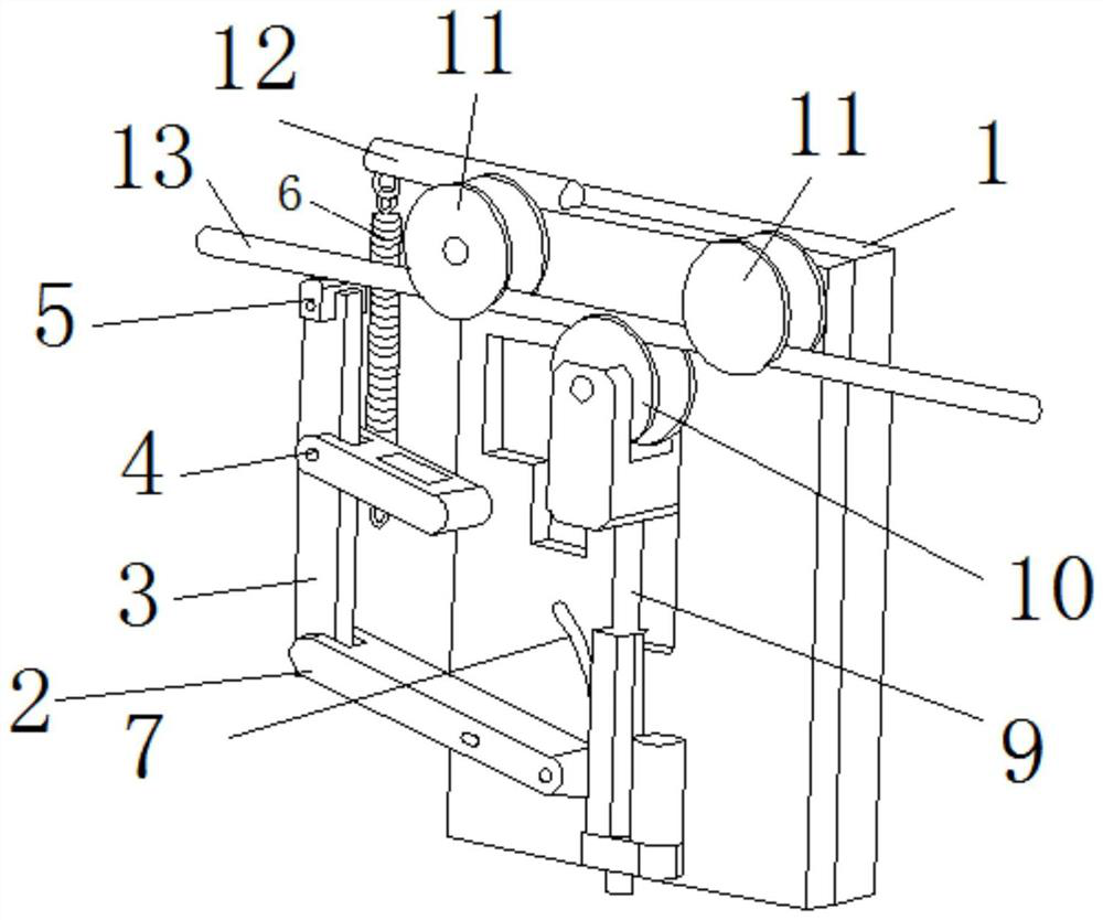
[0024] This embodiment proposes a high-voltage transmission line deicer, such as figure 1 and 2 As shown, it includes a back plate 1, a first connecting rod 2, a second connecting rod 3, a third connecting rod 4, a hammer body 5, a first elastic element 6, an arc-shaped slot 7, a pin 8, a lifting motor 9, a first Two rollers 10, first roller 11, fixed shaft 12, linear motor 14, cam 15, rotating motor 16, second elastic element 17, second contact sensor 18, first contact sensor 19, shifting block 20.

[0025] Wherein the first roller 11 and the second roller 10 are arranged up and down, and both are arranged on the front of the backboard 1 , the number of the first ro...


PUM


Abstract

The present invention proposes a high-voltage transmission line deicer, which includes a back plate and a first connecting rod, both of which are connected in rotation, and also includes: a second connecting rod, one end of which is connected in rotation with one end of the first connecting rod, and the other end It has a hammer body; an arc-shaped through groove is arranged on the back plate, and its track point gradually approaches the second connecting rod from bottom to top; a rotating block is installed on the back plate and carries the first connecting rod. The end of a connecting rod moves along the arc-shaped slot. The present invention is different from the prior art in that it changes the operation mode of the traditional mechanical deicer by scraping off the icing layer, and uses a hammering method instead, effectively and quickly knocking out the icing layer attached to the wire, and can target most It is applicable to most occasions, and the traveling mechanism provided by the application can effectively withstand the back of the electric wire segment when striking, and can make the strength of the ice hammer fully act on the ice layer.

Description

technical field [0001] The invention relates to the field of machinery, in particular to a deicer for high-voltage transmission lines. Background technique [0002] Because high-voltage transmission lines are generally erected at high altitudes, some areas in northern and southern my country are very cold in winter, and some areas have icing on overhead power transmission lines due to specific meteorological reasons. When the ice layer reaches a certain thickness, it must be removed, otherwise it will cause the power line to be broken and cause a power outage, seriously affecting industrial production and life. [0003] In the prior art, in order to solve this problem, there are mainly three kinds of deicing methods, electric heating deicing, manual deicing and mechanical deicing. in: [0004] First of all, the principle of electrothermal ice melting is to short-circuit the user end of the transmission line, reduce the power supply voltage through a step-down transformer, ...

Claims


Application Information

Patent Timeline
Patent Type & Authority Patents(China)
IPC IPC(8): H02G7/16H02G1/02
CPCH02G7/16H02G1/02
Inventor 吴斌张燕张艳萍雷磊顾剑顾本洪杨秀科潘存柱张贵平王秀境方学智
Owner GUIZHOU POWER GRID CO LTD
Why Eureka
Try Eureka