Self-heat-dissipation type power adapter

A power adapter, self-cooling technology, applied in the direction of electrical components, chemical instruments and methods, power electronics modification, etc., can solve the problems of reducing the dust resistance of the power adapter, reducing the portability of the power adapter, increasing the volume of the power adapter, etc. The effect of improving heat absorption, improving dust resistance, and increasing volume

Active Publication Date: 2021-01-26
深圳市英辉源电子有限公司
View PDF22 Cites 0 Cited by
  • Summary
  • Abstract
  • Description
  • Claims
  • Application Information

AI Technical Summary

Problems solved by technology

[0003] Common power adapters use fans or cooling holes for heat dissipation, and installing a cooling fan on the power adapter will undoubtedly increase the size of the power adapter and reduce the portability of the power adapter. Even when the temperature of the power adapter is low and there is no need for heat dissipation, dust can still enter the inside of the power adapter through the air outlet or cooling holes. Therefore, we propose a self-cooling power adapter

Method used


Image

  • Self-heat-dissipation type power adapter
  • Self-heat-dissipation type power adapter
  • Self-heat-dissipation type power adapter

Examples


Embodiment 1

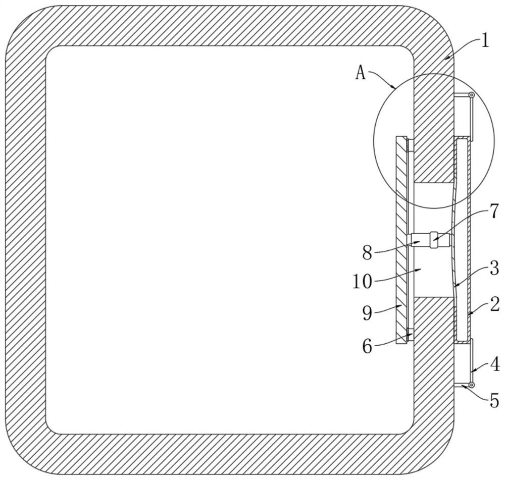
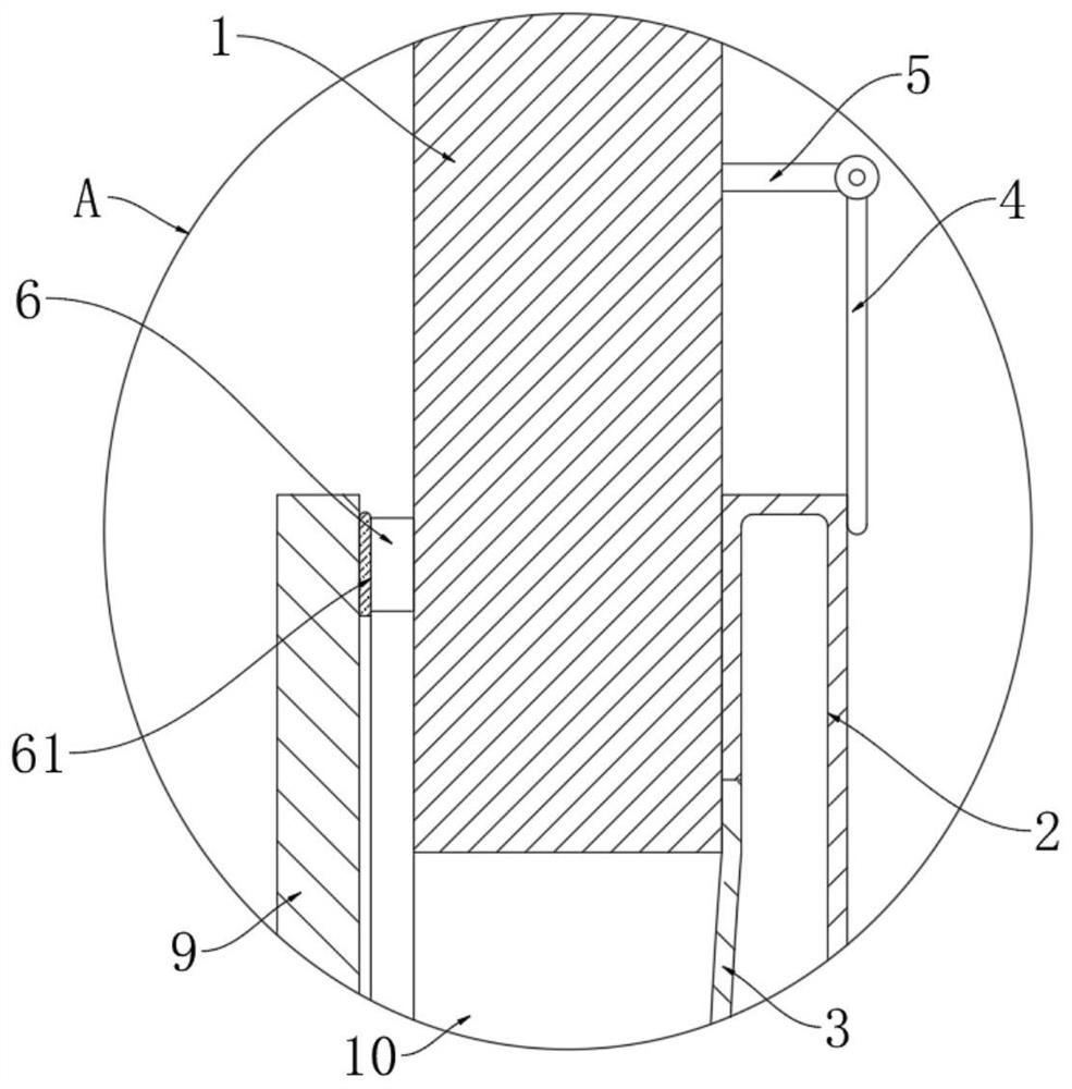
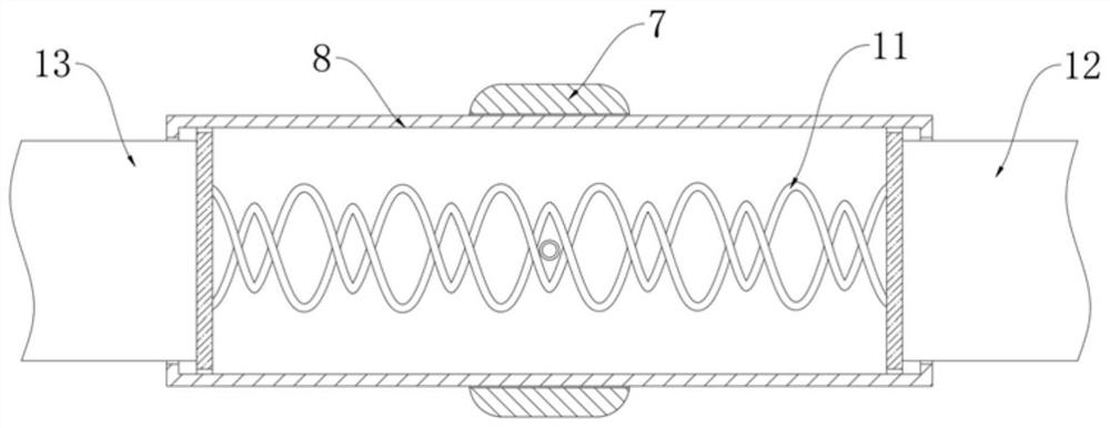
[0027] refer to Figure 1-5 , a self-radiating power adapter, including a housing 1, a heat dissipation hole 10 is opened through the side wall of the housing 1, a straight cylinder 8 is fitted in the heat dissipation hole 10 through a fixing part 7, and a thermal deformation is provided in the straight cylinder 8. 11, and the middle part of the heat-deformable part 11 is elastically connected to the inner wall of the straight cylinder 8. The heat-deformable part 11 is made of a memory alloy. When the temperature reaches the transformation temperature of the memory alloy, the heat-deformable part 11 will change from a contracted state to a stretched state , both ends of the thermally deformable member 11 are respectively fixedly connected with a first heat conduction rod 12 and a second heat conduction rod 13, and both the first heat conduction rod 12 and the second heat conduction rod 13 are slidingly connected with the straight cylinder 8;

[0028] The outer side of the hous...

Embodiment 2

[0035] refer to Figure 6-7 The difference between this embodiment and Embodiment 1 is that two sealing grooves 14 are symmetrically opened in the side wall of the housing 1, and a sliding plug 15 is arranged for sealing and sliding in each sealing groove 14, and each sealing groove 14 is close to One end of the cooling hole 10 is communicated with the cooling hole 10 through the air duct 16;

[0036] One end of the air duct 16 close to the heat dissipation hole 10 is arc-shaped, and is inclined to the outside of the heat dissipation hole 10 .

[0037] In this embodiment, each sealing groove 14 is provided with an expansion medium, and the expansion medium is located on the side of the corresponding slide plug 15 away from the cooling hole 10, and each air duct 16 is provided with a pressure valve. Dust-proof nets are clamped in the air ducts 16 to improve the dust-proof capability of the air ducts 16 .

[0038] When used in this embodiment, the expansion medium can be a low...


PUM


Abstract

The invention discloses a self-heat-dissipation type power adapter which comprises a shell, and a heat dissipation hole is formed in the side wall of the shell in a penetrating mode; a straight cylinder is arranged in the heat dissipation hole in an interference fit mode through a fixing piece, a thermal deformation piece is arranged in the straight cylinder, and the middle of the thermal deformation piece is elastically connected with the inner wall of the straight cylinder; a first heat conduction rod and a second heat conduction rod are fixedly connected to the two ends of the thermal deformation piece correspondingly and are both slidably connected with the straight cylinder, a cover plate is arranged on the outer side of the shell, one side wall of the cover plate is composed of an elastic layer, and the end, located on the outer side of the shell, of the first heat conduction rod is fixedly connected with the elastic layer; an annular check ring and a heat conduction plate are arranged on the inner side of the shell, and the annular check ring is fixedly connected with the inner side wall of the shell. The size of the power adapter cannot be greatly increased, no noise is generated during heat dissipation, and meanwhile, when the temperature of the power adapter is relatively low, the shell is in a completely closed state, and no dust enters the shell.

Description

technical field [0001] The invention relates to the technical field of power supplies, in particular to a self-radiating power adapter. Background technique [0002] The power adapter is a power supply conversion device, as long as the function is to convert AC input into AC output, so that the electrical equipment can be charged or work normally. [0003] Common power adapters use fans or cooling holes for heat dissipation, and installing a cooling fan on the power adapter will undoubtedly increase the size of the power adapter and reduce the portability of the power adapter. Even when the temperature of the power adapter is low and there is no need for heat dissipation, dust can still enter the inside of the power adapter through the air outlet or cooling holes. Therefore, we propose a self-cooling power adapter. Contents of the invention [0004] The purpose of the present invention is to solve the shortcomings in the prior art that installing a cooling fan on the powe...

Claims


Application Information

Patent Timeline
Patent Type & Authority Applications(China)
IPC IPC(8): H05K5/02H05K5/06H05K7/20B08B5/02H02M1/00
CPCH05K7/2089H05K7/20945H05K5/0213H05K5/0217H05K5/069H02M1/00B08B5/02H05K5/03
Inventor 王磊
Owner 深圳市英辉源电子有限公司
Why Eureka
Try Eureka