Supercharge Your Innovation With Domain-Expert AI Agents!

Turbine shaft, supercharger, and method for manufacturing supercharger

A turboshaft and supercharger technology, applied in engine manufacturing, pump components, engine components, etc., can solve problems such as weakening of nut holding force and deviation of rotation direction

Active Publication Date: 2021-01-26
MITSUBISHI HEAVY IND ENGINE & TURBOCHARGER LTD
View PDF11 Cites 0 Cited by
  • Summary
  • Abstract
  • Description
  • Claims
  • Application Information

AI Technical Summary

Problems solved by technology

If the compressor wheel shrinks in the axial direction, the holding force of the nut is weakened and the compressor wheel may be offset in the direction of rotation relative to the turbine shaft

Method used


Image

  • Turbine shaft, supercharger, and method for manufacturing supercharger
  • Turbine shaft, supercharger, and method for manufacturing supercharger
  • Turbine shaft, supercharger, and method for manufacturing supercharger

Examples


Embodiment Construction

[0054] Hereinafter, embodiments of the present invention will be described in detail with reference to the drawings.

[0055] However, the scope of the present invention is not limited to the following embodiments. The dimensions, materials, shapes, relative arrangements, and the like of components described in the following embodiments are not intended to limit the scope of the present invention thereto, but are merely illustrative examples.

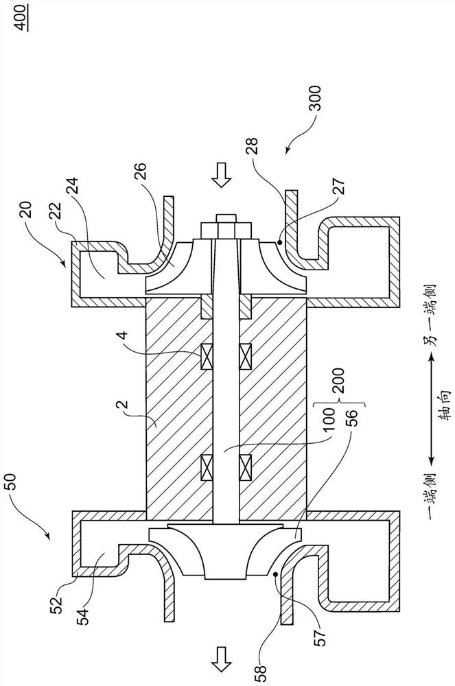
[0056] figure 1 It is a schematic cross-sectional view showing the structure of a supercharger 400 according to one embodiment of the present invention. use figure 1 , the outline of the supercharger 400 according to one embodiment of the present invention will be described. A supercharger 400 according to one embodiment of the present invention includes a turbine 50 and a compressor 20 .

[0057] The supercharger 400 has a turbine shaft 100 that is positioned between the turbine 50 and the compressor 20 and that connects a turbine ...


PUM


Abstract

A turbine shaft used for a supercharger provided with a turbine and a compressor is provided with a turbine impeller and a turbine shaft which has one end side to which the turbine impeller is joined.The turbine shaft includes a tapered section including: a fitting portion formed on the other end side of the turbine shaft and configured to be inserted into a through-hole in the compressor impeller of the compressor and fitted to the compressor impeller; and a fastening portion formed closer to the other end side of the turbine shaft than the fitting portion and configured so that a fasteningmember can be fastened thereto. The tapered section has a maximum outer diameter at the part of the fitting portion, which is located closest to the turbine impeller, and the tapered section is formedso that the outer diameter of the turbine shaft decreases from the part closest to the turbine impeller toward the front end of the compressor impeller.

Description

technical field [0001] The invention relates to a turboshaft assembly, a supercharger and a method for manufacturing the supercharger. Background technique [0002] Currently, in a typical supercharger, a turbine wheel is engaged on one end side of the turbine shaft, and a compressor wheel is mounted on the other end side of the turbine shaft. The integral part of the turbine shaft and the turbine impeller is called a turbine shaft assembly (タービンシャフト, turbine shaft). An external thread is cut out at the front end portion on the other end side of the turbine shaft, and is inserted into a through-hole formed in the compressor impeller from the back side of the compressor impeller. At this time, the end surface on the back side of the compressor impeller is brought into contact with a bush attached to the turbine shaft of the turbine shaft assembly or a flange portion formed on the turbine shaft. Then, a nut is attached to an external thread cut out on the other end side of t...

Claims


Application Information

Patent Timeline
Patent Type & Authority Applications(China)
IPC IPC(8): F02B39/00
CPCF02B37/00F02C6/12F01D5/025F05D2220/40F05D2250/292F05D2250/232F05D2260/31Y02T10/12F01D9/026F02B39/00F04D29/266F04D29/284F05D2240/60
Inventor 藤田豊段本洋辅
Owner MITSUBISHI HEAVY IND ENGINE & TURBOCHARGER LTD
Features
  • R&D
  • Intellectual Property
  • Life Sciences
  • Materials
  • Tech Scout
  • Unparalleled Data Quality
  • Higher Quality Content
  • 60% Fewer Hallucinations
Learn More