
Quick cold and hot water dispenser

A water dispenser, hot and cold technology, applied in beverage preparation devices, household appliances, applications, etc., can solve the problems of long waiting time for ice water, energy consumption, large consumption, etc. The effect of reducing and fully utilizing energy

Pending Publication Date: 2021-01-29
XIAMEN AOHUASI ELECTRIC
View PDF0 Cites 2 Cited by
  • Summary
  • Abstract
  • Description
  • Claims
  • Application Information

AI Technical Summary

Problems solved by technology

[0002] In the prior art, conventional ice water machines generally use refrigeration compressors, condensers, and evaporators to form a refrigeration system loop, and use external heat transfer to produce ice water. When cold water needs to be prepared, it needs to be started first. The refrigeration system can only be used when the temperature of the water source stored in the cold water tank meets the requirements; thus, it has the disadvantage of too long preparation time for cold water, and the waiting time is too long when drinking ice water is required, and it cannot meet the demand in time when the consumption is large
In addition, the long-term use of the refrigeration system will also cause energy consumption, which cannot meet the needs of energy-saving and environmental protection in modern life; and the refrigeration process is very noisy, which affects the user's life experience
[0003] Existing technology all is the water dispenser of room temperature water and hot water integration, lacks the water dispenser of ice water and hot water integration, is not enough to satisfy more diverse demand, the author of the present invention has been through research and practice for a long time Finally got the invention

Method used


Image

  • Quick cold and hot water dispenser
  • Quick cold and hot water dispenser
  • Quick cold and hot water dispenser

Examples


Embodiment Construction

[0038] The preferred embodiments of the present invention will be described in detail below in conjunction with the accompanying drawings, so that the advantages and features of the present invention can be more easily understood by those skilled in the art, so as to define the protection scope of the present invention more clearly.

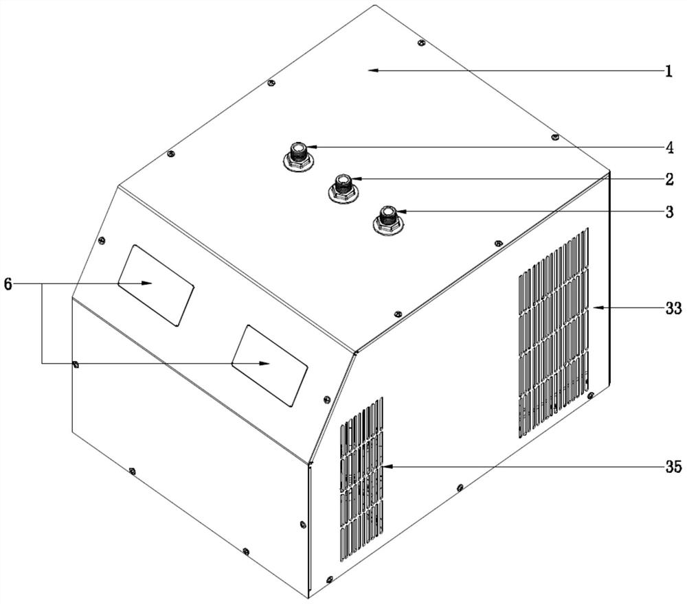
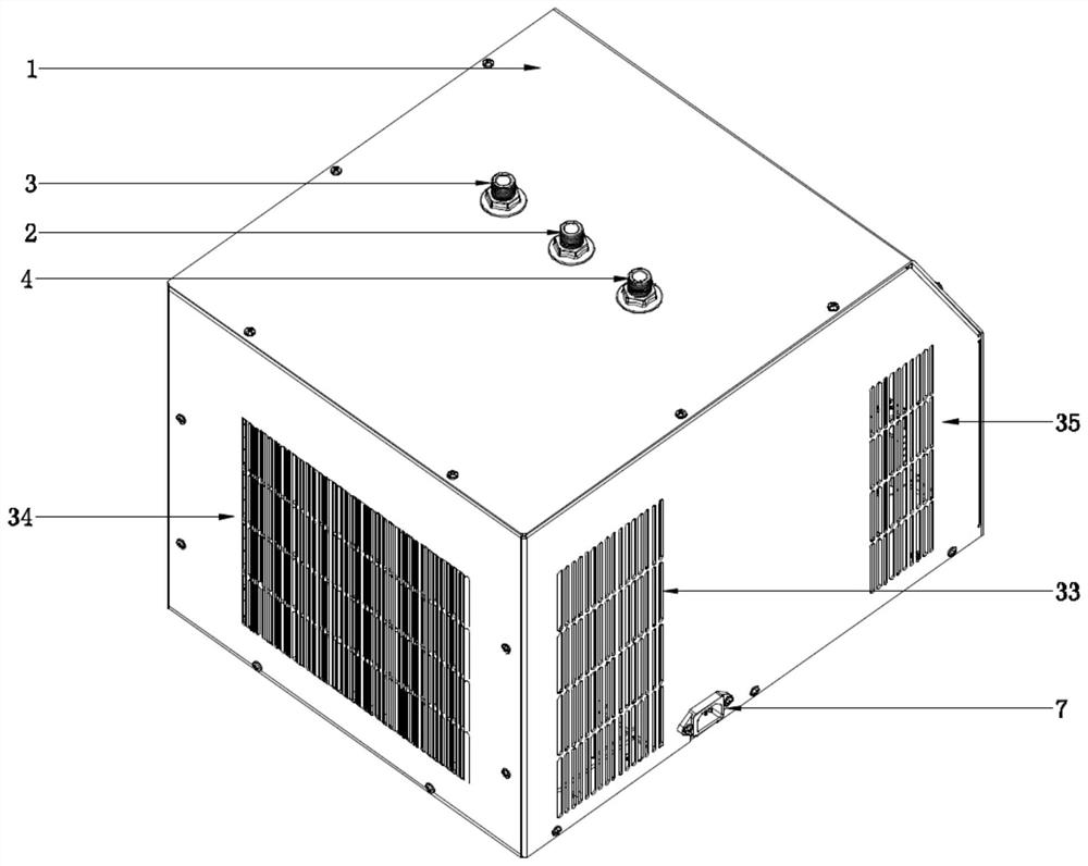
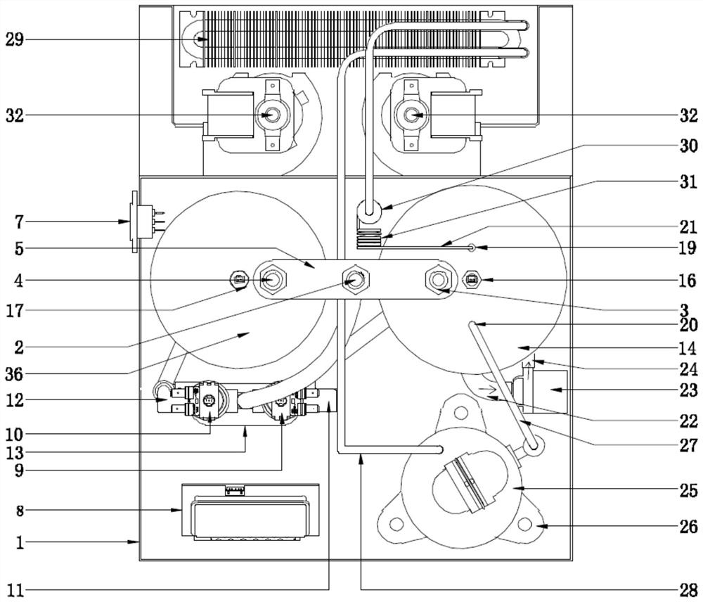
[0039] Such as Figure 1-8 As shown, a fast hot and cold water dispenser of the present invention includes a housing 1, a Venturi I11, a Venturi II12, a return chamber 13, a compressor 25, a condenser 29, an ice bucket 14, a heating liner 36 and an electronic controller 8 ;

[0040] The top of the housing 1 is provided with a normal temperature water inlet 2, an ice water outlet 3 and a hot water outlet 4, and a fixed water inlet 2, an ice water outlet 3 and a hot water outlet 4 are arranged between Bracket 5, a display screen 6 is installed on the front side of the housing 1, and a power base 7 is provided at the lower left side of the housing ...


PUM


Abstract

The invention discloses a quick cold and hot water dispenser. The quick cold and hot water dispenser comprises a shell, a venturi, a backflow cavity, a compressor, a condenser, an ice water bucket, aheating inner container and an electronic controller. A normal-temperature water inlet, an ice water outlet and a hot water outlet are formed in the upper portion of the shell, a fixing support is arranged among the normal-temperature water inlet, the ice water outlet and the hot water outlet, a display screen is installed on the front side of the shell, and a power supply base is arranged at thelower end of the left side of the shell. An electronic controller is fixed in the shell through a mounting bracket. An electromagnetic valve I and an electromagnetic valve II are arranged at the upperpart of the backflow cavity in parallel. Rapid refrigeration is realized by adopting an evaporation pipe built-structure, and requirements for rapid and large-quantity water are met; energy is fullyutilized and saved; a cold water barrel is provided with an internal circulating water device to prevent internal local areas from icing and achieve the effect of balanced cooling of water temperature; a cross-flow fan is adopted for heat dissipation of a condenser, and therefore, noise is lower, and comfort is higher.

Description

technical field [0001] The invention relates to the field of ice water machines, in particular to a fast hot and cold water dispenser. Background technique [0002] In the prior art, conventional ice water machines generally use refrigeration compressors, condensers, and evaporators to form a refrigeration system loop, and use external heat transfer to produce ice water. When cold water needs to be prepared, it needs to be started first. The refrigeration system can only be used when the temperature of the water source stored in the cold water tank reaches the required level; thus, it has the disadvantage of taking too long to prepare cold water, and the waiting time is too long when drinking ice water is required, and it cannot meet the demand in time when the consumption is large. In addition, the long-term use of the refrigeration system will also cause energy consumption, which cannot meet the needs of energy-saving and environmental protection in modern life; and the re...

Claims


Application Information

Patent Timeline
Patent Type & Authority Applications(China)
IPC IPC(8): A47J31/00A47J31/44A47J31/54A47J31/56
CPCA47J31/00A47J31/44A47J31/54A47J31/56
Inventor 戴锦塘
Owner XIAMEN AOHUASI ELECTRIC
Learn More