
Robot movable type automatic pressing rivet nut feeding and riveting mechanism

A technology of riveting mechanism and riveting nut, applied in metal processing equipment, feeding device, positioning device, etc., can solve the problems of wide area, poor product compatibility, large shape of riveted products, etc. High riveting quality and compact structure

Pending Publication Date: 2021-01-29
SUZHOU SIMITCH MASCH CO LTD
View PDF0 Cites 0 Cited by
  • Summary
  • Abstract
  • Description
  • Claims
  • Application Information

AI Technical Summary

Problems solved by technology

[0002] In the manufacture of automated equipment, different parts / plates need to be riveted by pressure riveting. The existing technology is realized by riveting special machines. For products, there are fixed riveting joints at corresponding positions. Since the riveting positions of various products are different, the required riveting The product has a large shape, which makes the riveting machine larger in size. The applicable product type is relatively single, and the product compatibility is poor. Different products require a variety of different riveting machines. The investment in equipment is large and the area is large. Due to the The riveting angle is fixed, and the riveting angles at different points are the same, but the riveting angles of the workpiece itself are slightly different, resulting in poor riveting effect and unstable quality

Method used


Image

  • Robot movable type automatic pressing rivet nut feeding and riveting mechanism
  • Robot movable type automatic pressing rivet nut feeding and riveting mechanism
  • Robot movable type automatic pressing rivet nut feeding and riveting mechanism

Examples


Embodiment Construction

[0018] The technical solutions in the embodiments of the present invention will be described in detail below in conjunction with the accompanying drawings in the embodiments of the present invention. Obviously, the described embodiments are only some of the embodiments of the present invention, not all of them. Based on the embodiments of the present invention, all other embodiments obtained by persons of ordinary skill in the art without making creative efforts belong to the protection scope of the present invention.

[0019] In the description of the present invention, it should be noted that the terms "center", "upper", "lower", "left", "right", "vertical", "horizontal", "inner", "outer" etc. The indicated orientation or positional relationship is based on the orientation or positional relationship shown in the drawings, and is only for the convenience of describing the present invention and simplifying the description, rather than indicating or implying that the referred de...


PUM


Abstract

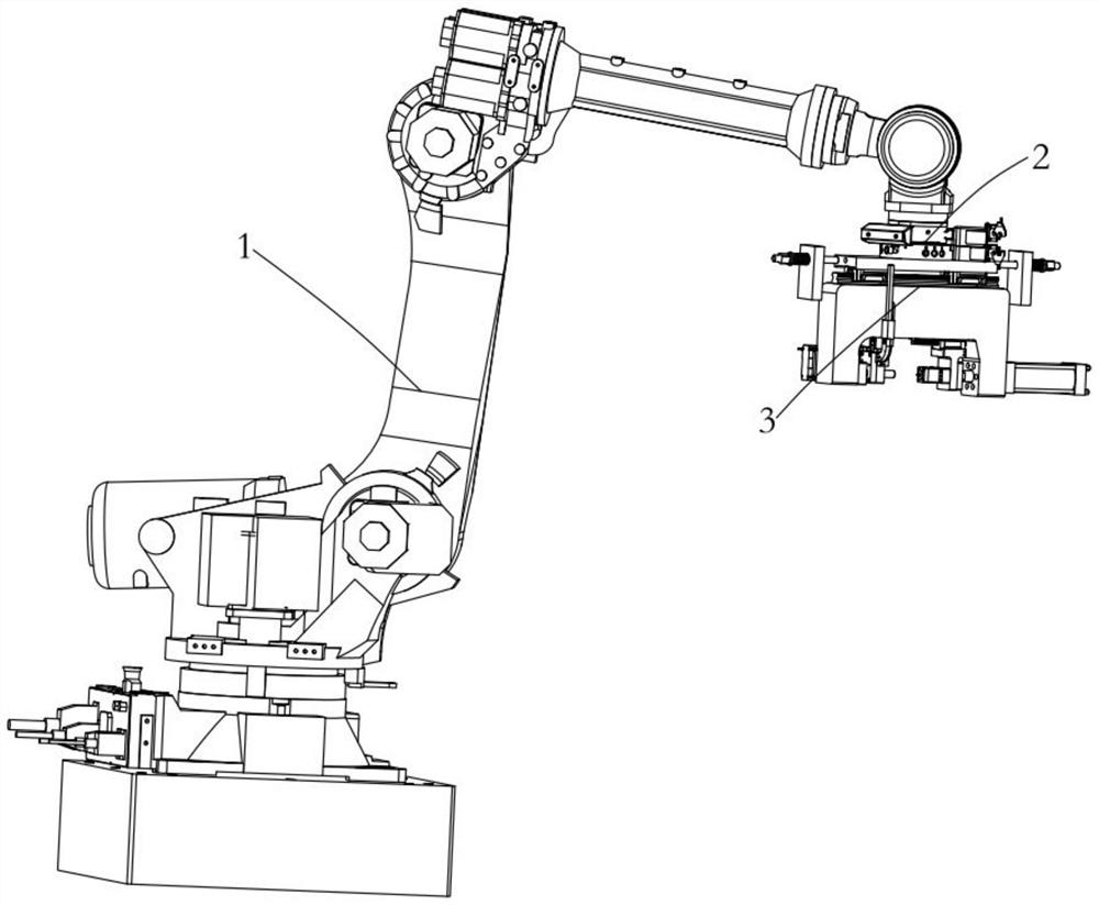
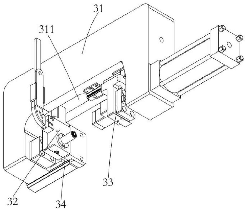
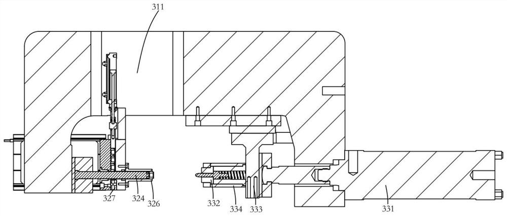
The invention discloses a robot movable type automatic pressing rivet nut feeding and riveting mechanism which comprises a robot. A wrist of the robot is directly connected with a feeding and rivetingmechanism or connected with the feeding and riveting mechanism through a floating connecting piece; the feeding and riveting mechanism comprises a clamp body, a feeding mechanism and a press-fittingmechanism; the feeding mechanism and the press-fitting mechanism are oppositely arranged at two ends of the clamp body; the feeding mechanism is connected to the clamp body in a sliding mode through apushing air cylinder and comprises a feeding block communicating with an external vibration disc through a feeding pipe, a pressing air cylinder fixed to the top end of the feeding block and a riveting rod penetrating through the feeding block in a sliding mode; the press-fitting mechanism comprises a pressurized cylinder fixed to the clamp body and a press-fitting head connected to the piston end of the pressurized cylinder; and the pressurized cylinder, the press-fitting head and the riveting rod are coaxially arranged. The mechanism can be installed on a robot, the convenience in moving and riveting is realized, nuts can be automatically conveyed, and the production efficiency is improved; and equipment operation has low technical requirements on personnel, and so that operation is conducted simply and flexibly.

Description

technical field [0001] The present application relates to the field of automated machinery, in particular to a riveting mechanism for automatic feeding of riveting nuts with mobile robots. Background technique [0002] In the manufacture of automated equipment, it is necessary to perform pressure riveting on different parts / plates. The existing technology is realized by riveting special machines. For products, there are fixed riveting joints at corresponding positions. Since the riveting positions of various products are different, the required riveting The product has a large shape, which makes the riveting machine larger in size, and the applicable product types are relatively single, and the product compatibility is poor. Different products require a variety of different riveting machines, which requires a large investment in equipment and a large area. The riveting angle is fixed, and the riveting angles at different points are the same, but the riveting angles of the wo...

Claims


Application Information

Patent Timeline
Patent Type & Authority Applications(China)
IPC IPC(8): B21D39/00B21D43/10
CPCB21D39/00B21D43/105
Inventor 张伦伦金涛曾祥迅
Owner SUZHOU SIMITCH MASCH CO LTD
Learn More