Straight workpiece arc angle cutting tool

A cutting tool and arc angle technology, which is applied in the field of arc angle cutting tools for straight workpieces, can solve the problems of arc angle machining accuracy and low efficiency.

Active Publication Date: 2021-01-29
JIANGSU SECURITY TECH CARRER ACADEMY
View PDF7 Cites 0 Cited by
  • Summary
  • Abstract
  • Description
  • Claims
  • Application Information

AI Technical Summary

Problems solved by technology

[0003] The invention provides a straight workpiece arc angle cutting tool, which can solve the problem of low machining accuracy and efficiency of arc angle in mass production

Method used


Image

  • Straight workpiece arc angle cutting tool
  • Straight workpiece arc angle cutting tool
  • Straight workpiece arc angle cutting tool

Examples


Embodiment 1

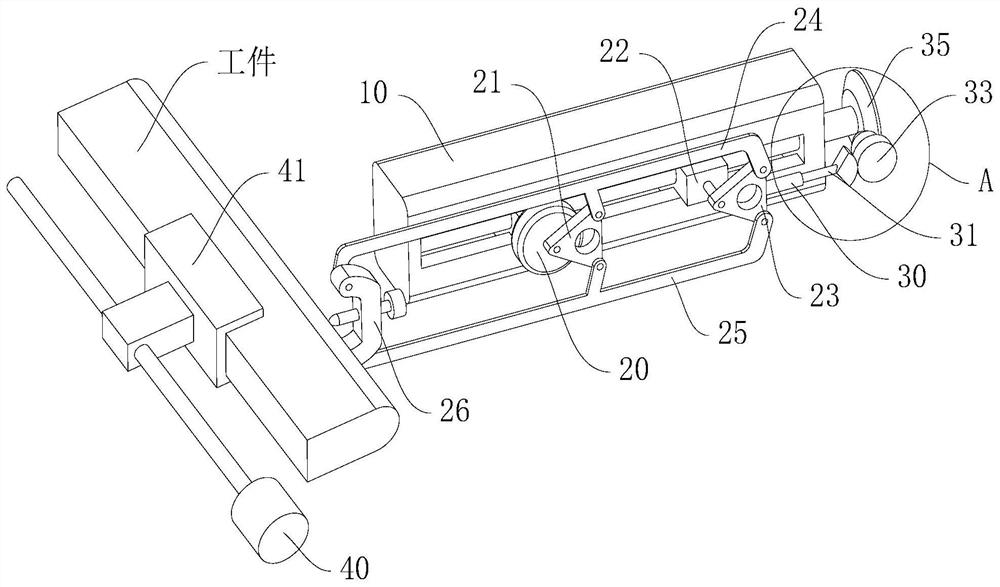
[0025] Such as Figure 1 to Figure 6 As shown, a straight workpiece arc angle cutting tool provided by an embodiment of the present invention includes:

[0026] Drive mechanism, it comprises driving motor 40, driving screw and clamping device 41, and clamping device 41 is used for clamping workpiece, and driving screw is matched with clamping device 41, is used to drive clamping device 41 to move, and drive motor 40 is used to drive the screw to rotate; wherein, the clamping device 41 can adopt a clamping device in the prior art, such as a bolt clamping method.

[0027] Grinding mechanism, it comprises base 10, grinding motor 20, first rotating block 21, second rotating block 23, first turning bar 24, second turning bar 25 and knife rest 26, and knife rest 26 is used for installing cutter , the grinding motor 20 is fixedly arranged on the base 10, the first rotating block 21 is transmission-connected to the output end of the grinding motor 20, and the second rotating block 23...

Embodiment 2

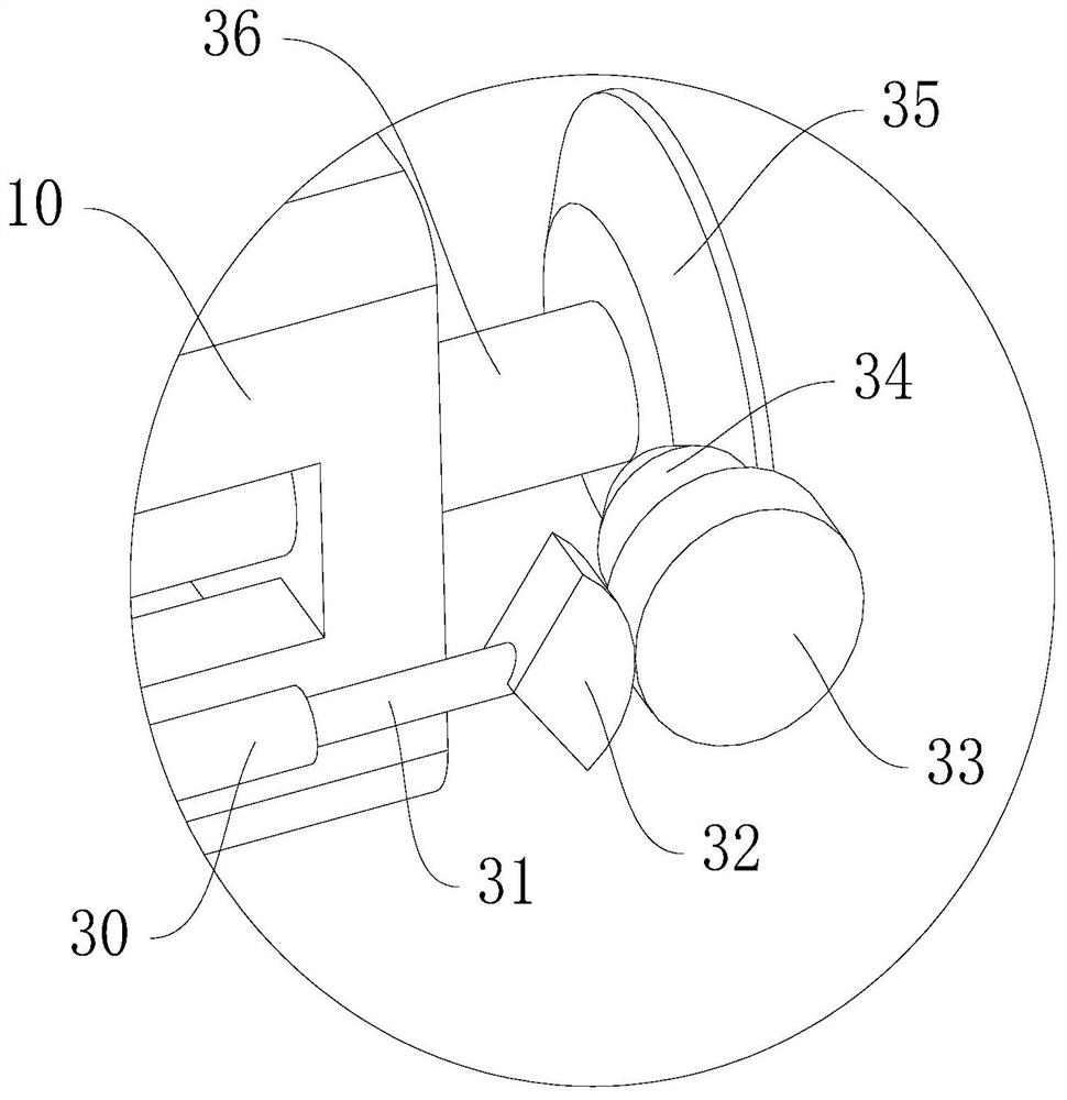
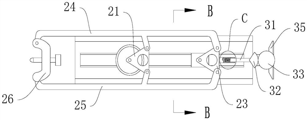
[0031] In the first embodiment, only the workpiece that has been cast can be corrected to achieve higher precision, but when it is completely dependent on the cutting process for forming, the progressive feed of the tool is required, so on the basis of the first embodiment , the present embodiment also includes a feed mechanism, which includes a first slide block, a second slide block 22, an arc block 32, a drive wheel 33, a first bevel gear 34, a second bevel gear 35 and a feed screw 36, basically Offer feed chute on seat 10, as Figure 5 As shown, the feed chute is T-shaped, and the cross-sections of the first slider and the second slider 22 are also T-shaped, and the first slider and the second slider 22 can be slidably arranged in the feed chute , the first slider and the second slider 22 are provided with threaded holes that match the feed screw 36, and when the feed screw 36 rotates, it drives the first slider and the second slider 22 to move synchronously; the grinding ...

Embodiment 3

[0037]On the basis of Embodiment 1 or Embodiment 2, after the cutting is in place, it is generally necessary to reciprocate the incision for a period of time without feeding to clean up the cut marks or burrs of the incision. In addition, in some workpieces, such as unqualified parts When correcting, continuous feeding is often not required, so it is necessary to be able to switch between feeding and non-feeding states, so this embodiment also includes a control system, which includes a processor, a wireless transmitting module, a wireless receiving module 52 and The electromagnet 50 , the wireless transmitting module, the wireless receiving module 52 , the electromagnet 50 and the grinding motor 20 are all signal-connected to the processor, and the electromagnet 50 is fixedly arranged in the sliding sleeve 30 for absorbing the sliding rod 31 .

[0038] In the feed state, the electromagnet 50 is de-energized, and the working process is the same as in the second embodiment. Whe...


PUM


Abstract

The invention discloses a straight workpiece arc angle cutting tool, and belongs to the field of machining. The device comprises a driving mechanism and a grinding mechanism, wherein the driving mechanism comprises a driving motor, a driving lead screw and a clamping device; the grinding mechanism comprises a base, a grinding motor, a first rotating block, a second rotating block, a first overturning rod, a second overturning rod and a cutter rest, the cutter rest is used for installing a tool, the grinding motor is fixedly arranged on the base, the first rotating block is in transmission connection with the output end of the grinding motor, the second rotating block is rotationally arranged on the base, one end of the first overturning rod is hinged to the second rotating block, the otherend of the first overturning rod is hinged to the cutter rest, the middle of the first overturning rod is hinged to the first rotating block, one end of the second overturning rod is hinged to the second rotating block, the other end of the second overturning rod is hinged to the cutter rest, and the middle of the second overturning rod is hinged to the first rotating block. According to the straight workpiece arc angle cutting tool, the machining efficiency is improved, due to machining, the machining precision can be obviously improved, and the cut arc is regular and smooth.

Description

technical field [0001] The invention relates to the field of machining, in particular to a straight workpiece arc angle cutting tool. Background technique [0002] In the machining and manufacturing process, it is often necessary to perform arc chamfering operations on workpieces. In the prior art, it is generally formed through molding, such as one-time molding during casting, or manually polished. However, for high precision requirements and large batches, the efficiency of manual grinding is low, and the general precision of casting molding is difficult to meet the requirements. Contents of the invention [0003] The invention provides an arc angle cutting tool for straight workpieces, which can solve the problems of low machining accuracy and efficiency of arc angles during mass production. [0004] A straight workpiece arc angle cutting tool, comprising: [0005] The driving mechanism includes a driving motor, a driving screw and a clamping device, the clamping dev...

Claims


Application Information

Patent Timeline
IPC IPC(8): B23D79/00
CPCB23D79/00Y02P70/10
Inventor 侯玉洁杨炎川
Owner JIANGSU SECURITY TECH CARRER ACADEMY
Why Eureka
Try Eureka