
Electric driving system and electric vehicle

A technology for electric drive systems and electric vehicles, applied to vehicle components, electric power devices, power devices, etc., can solve the problems of high motor power and low efficiency, and achieve the effects of weight reduction, flexible energy recovery, and volume reduction

Active Publication Date: 2021-01-29
ZHENGZHOU YUTONG BUS CO LTD
View PDF8 Cites 2 Cited by
  • Summary
  • Abstract
  • Description
  • Claims
  • Application Information

AI Technical Summary

Problems solved by technology

[0003] The purpose of the present invention is to provide an electric drive system to solve the problems of high motor power requirements and low efficiency in the existing electric drive systems

Method used


Image

  • Electric driving system and electric vehicle
  • Electric driving system and electric vehicle

Examples


Embodiment Construction

[0043]The embodiments of the present invention will be further described below in conjunction with the drawings.

[0044]The specific embodiment of the vehicle of the present invention includes a frame on which wheels are mounted via a suspension. The frame is also equipped with a power supply, an electric drive system and a control system.

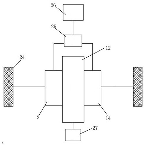
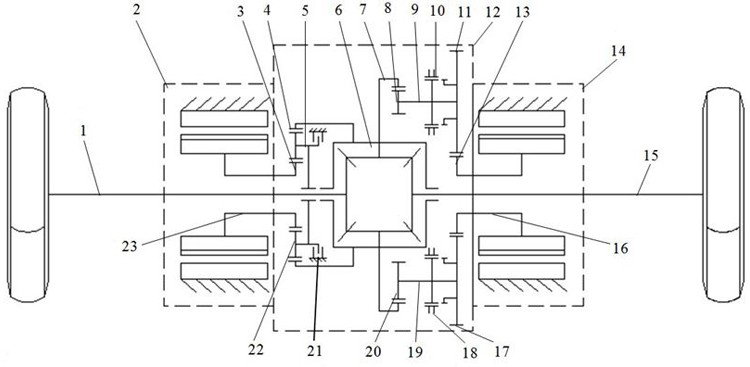
[0045]Such asfigure 1 Shown is a simplified diagram of the electric drive system of the vehicle of the present invention. It can be clearly seen from the figure that the electric drive system mainly includes a first motor 2, a second motor 14 and a speed change mechanism 12, the first motor, the second motor The motors are all drivingly connected to the speed change mechanism 12 and output torque to the wheels 24 through the speed change mechanism 12. The first motor 2 and the second motor 14 are arranged on opposite sides of the speed change mechanism 12. The shaft of the first motor 2 and the shaft of the second motor 14 are both hollow shafts for ...


PUM


Abstract

The invention relates to the field of pure electric vehicles, and in particular relates to an electric driving system and an electric vehicle. The electric driving system comprises a first motor, a second motor and a speed change mechanism. The speed change mechanism comprises a differential mechanism, a gear shifting mechanism and a planetary speed reducing mechanism. A first motor shaft of the first motor is connected with a sun gear of the planetary speed reducing mechanism, and a front gear ring of the planetary speed reducing mechanism is connected with the input end of the differential mechanism. A second motor shaft of the second motor is connected with the input end of the differential mechanism through the gear shifting mechanism; the two output ends of the differential mechanismdrive wheels to rotate through a left half shaft and a right half shaft respectively. A planet carrier of the planetary speed reducing mechanism is provided with a locking clutch so as to achieve locking and unlocking of the planet carrier. When the electric driving system is used on the vehicle, the requirement for motor power is low, cost is reduced, one motor can provide torque compensation forthe other motor during gear shifting, and power interruption is avoided; and the switching of working modes can be realized through the locking clutch.

Description

Technical field[0001]The invention relates to the field of pure electric vehicles, in particular to an electric drive system and an electric vehicle.Background technique[0002]At present, my country's electric vehicle power system mostly adopts single motor direct drive + drive axle, single motor + single-stage reducer, single motor + two-speed AMT gearbox. For electric vehicles that adopt single-motor direct drive + drive axle, single-motor + single-stage reducer, in order to take into account the performance requirements of both power and high-speed driving, the motor power needs to be large enough, and the high-power motor is expensive and heavy, and at the same time It is difficult for the motor to work in the high-efficiency area, which causes the vehicle to consume a lot of electricity and has a short driving range, which seriously affects the economy and power of the vehicle. For electric vehicles with a single-motor + two-speed AMT gearbox solution, although the motor can be ...

Claims


Application Information

Patent Timeline
Patent Type & Authority Applications(China)
IPC IPC(8): B60K1/02B60K17/04B60K17/08B60K17/16
CPCB60K1/02B60K17/04B60K17/08B60K17/165
Inventor 刘东方王印束高亚培程晓伟吴胜涛王彪牛绍和
Owner ZHENGZHOU YUTONG BUS CO LTD
Learn More