Furnace lining dismounting device for vacuum furnace

A vacuum furnace and furnace lining technology, applied in the direction of lifting devices, transportation and packaging, load hanging components, etc., can solve the problems of low production efficiency, high cost of leak detection and shutdown, and long shutdown time, so as to improve production efficiency , reduce the cost of leak detection and downtime, and reduce the effect of downtime

Pending Publication Date: 2021-01-29
湖州久立永兴特种合金材料有限公司
View PDF0 Cites 0 Cited by
  • Summary
  • Abstract
  • Description
  • Claims
  • Application Information

AI Technical Summary

Problems solved by technology

The shutdown time between the whole set of furnace operations is long, the production efficiency is low, and the cost of leak detection and shutdown is high. If a fault occurs, the molten steel freezing furnace needs to be cooled for more than 72 hours before it can be dismantled

Method used


Image

  • Furnace lining dismounting device for vacuum furnace
  • Furnace lining dismounting device for vacuum furnace
  • Furnace lining dismounting device for vacuum furnace

Examples


Embodiment 1

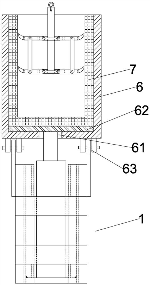
[0037]A furnace lining removal device in a vacuum furnace, comprising a lining ejection mechanism and a lining lifting mechanism; the lining ejection mechanism includes a positioning steel frame 1, a connecting plate 2 arranged on the top of the positioning steel frame for connecting the vacuum furnace, and An installation seat cavity 3 with an open upper end arranged in the steel frame, and a jack is arranged in the installation seat cavity; the furnace lining lifting mechanism includes a main hanger 4 and at least three circumferentially evenly distributed on the main hanger. A plurality of horizontal hanging claws 5, the main hanger and the horizontal hanging claw are hinged, the maximum angle between the horizontal hanging claw and the main hanger is 90 degrees, and the outer end of the horizontal hanging claw is provided with The claw end 54 is formed by extending outward and upward in an arc.

[0038] When this application is in use, first place the jack vertically in th...

Embodiment 2

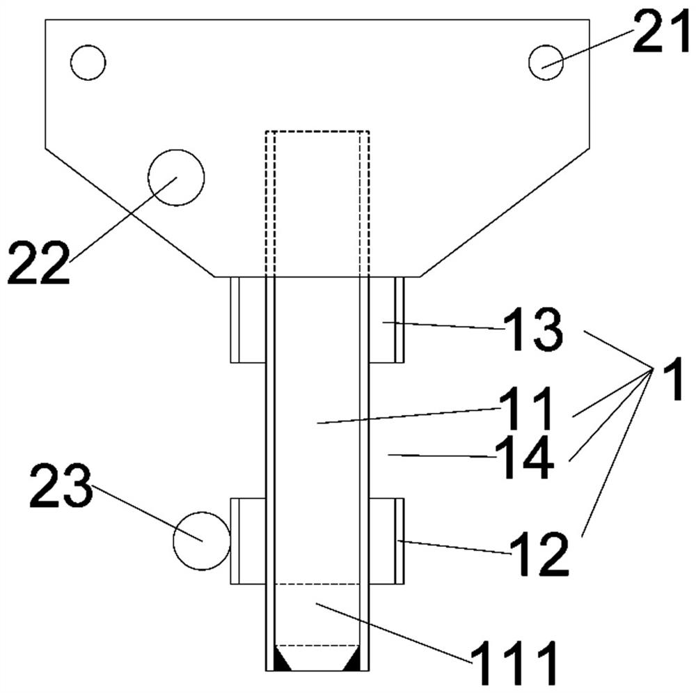
[0040] The difference from the above embodiment is that the positioning steel frame includes at least a pair of main columns 11 located opposite to the two sides of the mounting seat cavity, and a connecting piece 12 connected between the main columns, and the connecting plates are symmetrically arranged on a pair of There are two on the main column, and the connecting plate is arranged on the outside of the main column, the upper end of the connecting plate extends upward beyond the top of the main column, and at least two connecting holes 21 are opened on the protruding part of each connecting plate. The existing furnace shell is designed with its own rack slot for positioning when it is hoisted to the disassembly workshop. The connecting plate designed in this application is docked with the existing rack slot, so as to ensure that the lining ejection mechanism is installed stably, and the jack and furnace The alignment of the furnace mouth at the bottom is accurate, and the ...

Embodiment 3

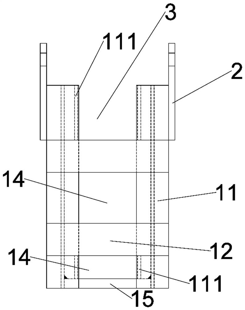
[0042] The difference from the above embodiment is that the positioning steel frame includes a pair of symmetrically arranged main columns, and the two sides of the main columns are correspondingly provided with pad width pieces 13, and the connecting piece is a pad connected to the two main columns. The bridge connecting plate between the wide pieces; on each side of the main column, at least two pad width pieces are arranged at intervals from top to bottom, and the bridging plates are at least two corresponding; the ones on the same side of the main column A communication port 14 is formed between the upper and lower bridging plates to connect the mounting cavity with the outside world, and / or a communication port is left between the bottom bridging plate and the bottom end of the main column to communicate the mounting cavity with the outside world .

[0043] The distance between the two main columns is first set according to the size required for the installation of the ja...


PUM


Abstract

The invention belongs to the field of steelmaking equipment, and particularly relates to a lining dismounting device for a vacuum furnace. The lining dismounting device comprises a furnace lining ejection mechanism and a furnace lining hoisting mechanism; the furnace lining ejection mechanism comprises a positioning steel frame, a connecting plate and a mounting seat cavity, and a jack is arrangedin the mounting seat cavity; the furnace lining hoisting mechanism comprises a main hoisting rod and at least three transverse hoisting claws evenly distributed on the main hoisting rod in the circumferential direction, the main hoisting rod is hinged to the transverse hoisting claws, the maximum included angle between the unfolded transverse hoisting claws and the main hoisting rod is 90 degrees, and the outer ends of the transverse hoisting claws are provided with claw ends extending outwards and upwards in an arc mode. According to the dismounting device, the furnace lining can be dismounted in the furnace within 8 hours or more after the furnace service is finished, an induction furnace does not need to be moved to another workshop for dismounting the furnace lining, the furnace shutdown time between the furnace service can be shortened after improvement, the production efficiency is improved, and the leakage detection and shutdown cost is reduced; and particularly, the dismounting time of the cold start boiler after a fault occurs can be greatly reduced.

Description

technical field [0001] The invention belongs to the field of steelmaking equipment, and in particular relates to a furnace lining removal device in a vacuum furnace. Background technique [0002] At present, the induction furnace needs to be cooled in the furnace for 48 hours after a furnace service is completed, and then disassembled and hoisted to the preparation workshop next door for furnace lining removal. After dismantling and cleaning, it is hoisted back to the original station for installation. After installation, the induction furnace still needs a day of pumping It takes 72 hours to remove and install the furnace in three shifts, and it takes 120 hours after the end of the furnace operation to complete the furnace lining after the leak detection. The shutdown time between the whole set of furnace operations is long, the production efficiency is low, and the cost of leak detection and shutdown is high. If a fault occurs, the molten steel freezing furnace needs to be...

Claims


Application Information

Patent Timeline
IPC IPC(8): B66C1/10B66C1/44B66F3/25B23P19/00C21C7/10
CPCB23P19/00B66C1/10B66C1/442B66F3/25C21C7/10
Inventor 吕惠杰王小萍董易淼吕东旭王旭朱雄明
Owner 湖州久立永兴特种合金材料有限公司
Why Eureka
Try Eureka