Top-mounted ultralow-temperature butterfly valve capable of being overhauled on line

An ultra-low temperature, installed technology, applied in the direction of valve lift, valve details, valve devices, etc., can solve the problems of reduced sealing effect, valve seal failure, and easy damage of the sealing ring, so as to improve the use performance, improve the sealing effect, high strength The effect of the sealing effect

Pending Publication Date: 2021-01-29
浙江富技阀门有限公司
View PDF0 Cites 0 Cited by
  • Summary
  • Abstract
  • Description
  • Claims
  • Application Information

AI Technical Summary

Problems solved by technology

[0003] Ordinary sealed butterfly valve body and valve plate are an integral installation structure, that is, the valve plate is directly sealed and installed in the valve body. Once the valve leaks, it can only be repaired by removing the valve from the pipeline, so it cannot be repaired or replaced online. , it is difficult to carry out on-site maintenance without affecting the use of the valve;
[0004] And the sealing ring materials used in the prior art are mostly multi-layer sealing rings made of flexible graphite sandwiched between stainless steel. Since flexible graphite is a soft non-metallic material, it is not resistant to medium erosion, so when the butterfly valve is used for a long time, the sealing ring will It is easy to be damaged, which will affect the sealing performance of the valve. In severe cases, it will lead to the failure of the valve seal. Especially for ultra-low temperature environments, the sealing ring is easy to shrink due to cold. When the sealing ring shrinks, its sealing effect with the inner wall of the valve will be greatly reduced

Method used


Image

  • Top-mounted ultralow-temperature butterfly valve capable of being overhauled on line
  • Top-mounted ultralow-temperature butterfly valve capable of being overhauled on line
  • Top-mounted ultralow-temperature butterfly valve capable of being overhauled on line

Examples


Embodiment 1

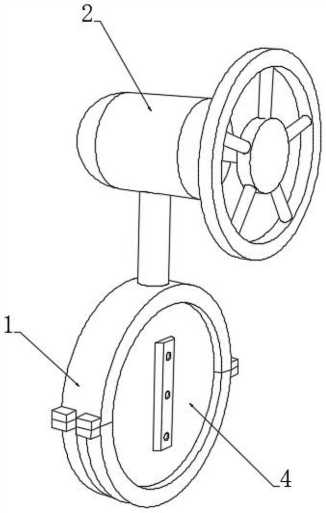
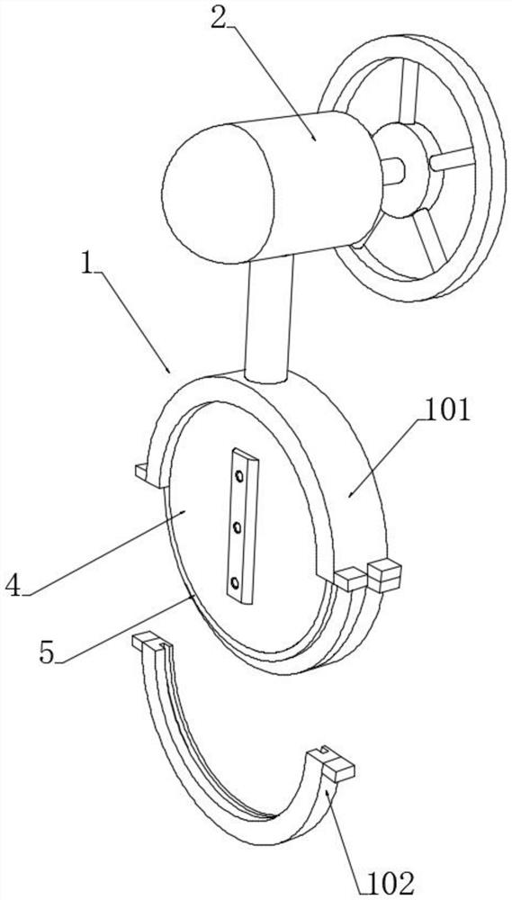
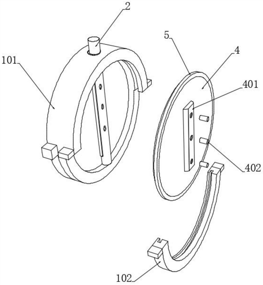
[0045] see Figure 1-7 , a top-mounted ultra-low temperature butterfly valve that can be repaired online, including a valve body 1 and a valve stem 3 rotatably installed in the valve body 1, and a valve cover 2 connected to the top of the valve stem 3 is installed on the valve body 1, and the valve cover 2 A turntable is provided on one side of the valve cover 2, and a drive structure to drive the rotation of the valve stem 3 is arranged inside the valve cover 2. The drive structure is connected with the turntable to realize the rotation of the valve stem 3 by operating the turntable. This is the prior art and will not be described here. To repeat too much, the valve body 1 includes a main valve body 101 and an auxiliary valve body 102 embedded on both sides of the bottom end of the main valve body 101. An arc-shaped embedded cavity is installed, and the valve stem 3 is fixedly installed with a valve plate 4 at the left and right ends of the valve body 1. The two valve plates ...


PUM


Abstract

The invention discloses a top-mounted ultralow-temperature butterfly valve capable of being overhauled on line, and belongs to the technical field of butterfly valves. A valve body is arranged to be of a structure comprising a main valve body and two detachable auxiliary valve bodies; valve plates corresponding to the two auxiliary valve bodies in position are installed on the two sides of a valverod; due to the arrangement of the two valve plates, the sealing effect of the valve plates is improved; meanwhile, the two valve plates are matched with the two detachable auxiliary valve bodies sothat the auxiliary valve bodies can be detached on line to overhaul the valve plates in the valve body; the butterfly valve does not need to be taken down from a pipeline in the overhaul process, andnormal use of the butterfly valve is not affected; in addition, a compensation cavity is formed in a sealing cavity of a sealing ring on the valve body; a cold expansion compensation layer tightly attached to the inner wall of the sealing ring is arranged in the compensation cavity; and during working in a low-temperature environment, the cold expansion compensation layer expands to a certain extent when meeting cold, so that the sealing ring is pushed to extrude outwards, the sealing degree of the sealing ring and the valve plates is effectively improved, and the sealing effect between the valve body and the valve plates cannot be affected by shrinkage of the sealing ring.

Description

technical field [0001] The invention relates to the technical field of butterfly valves, in particular to a top-mounted ultra-low temperature butterfly valve capable of on-line maintenance. Background technique [0002] Butterfly valve, also known as flap valve, is a regulating valve with simple structure, which can be used for switching control of low-pressure pipeline medium. of a valve. It can be used to control the flow of various types of fluids such as air, water, steam, various corrosive media, mud, oil, liquid metal and radioactive media. It mainly plays the role of cutting and throttling on the pipeline. [0003] Ordinary sealed butterfly valve body and valve plate are an integral installation structure, that is, the valve plate is directly sealed and installed in the valve body. Once the valve leaks, it can only be repaired by removing the valve from the pipeline, so it cannot be repaired or replaced online. , it is difficult to carry out on-site maintenance wit...

Claims


Application Information

Patent Timeline
Patent Type & Authority Applications(China)
IPC IPC(8): F16K1/22F16K1/226F16K1/48F16K27/02
CPCF16K1/22F16K1/222F16K1/2261F16K1/2263F16K1/48F16K27/0218
Inventor 刘智吴玉良张智博曹甲亮叶凯强
Owner 浙江富技阀门有限公司
Why Eureka
Try Eureka