
Floating ball type drain valve rod and double-valve-element assembly

A steam trap and double-spool technology, which is applied to steam traps, machine tools designed for grinding the rotating surface of workpieces, grinding machines, etc., can solve the problems of coaxiality that cannot meet the requirements and reduce the air tightness of steam traps, etc. Achieve high coaxiality and ensure the effect of coaxiality

Pending Publication Date: 2021-01-29
常州艾肯智造科技有限公司
View PDF0 Cites 0 Cited by
  • Summary
  • Abstract
  • Description
  • Claims
  • Application Information

AI Technical Summary

Problems solved by technology

The two valve cores are connected to the same valve stem, which requires extremely high precision of the valve core and the assembly quality of the valve core. If the airtightness of the trap is not met, the airtightness of the trap will be reduced

Method used

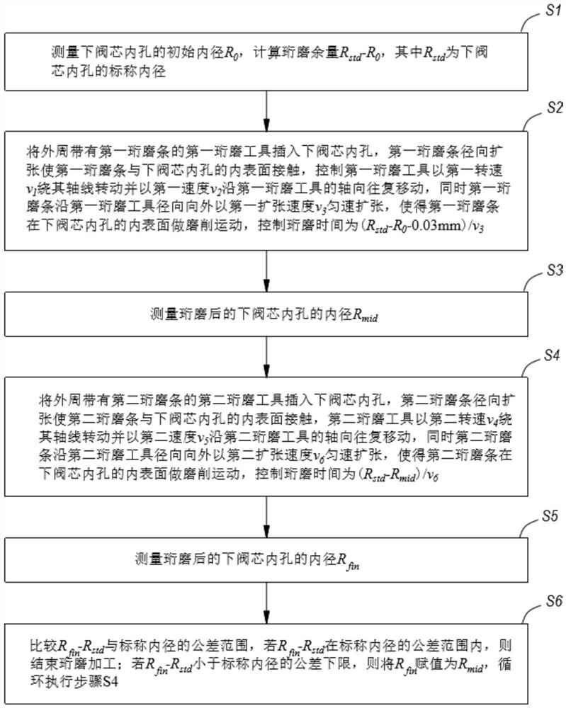

Image

  • Floating ball type drain valve rod and double-valve-element assembly
  • Floating ball type drain valve rod and double-valve-element assembly
  • Floating ball type drain valve rod and double-valve-element assembly

Examples


Embodiment Construction

[0043] The present invention will be described in further detail below in conjunction with the accompanying drawings.

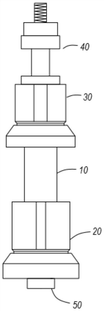
[0044] Please refer to figure 1 with figure 2 , Float trap valve stem and double spool assembly, including valve stem 10, lower spool 20, upper spool 30, fastening component 40 and screw 50. The lower valve core 20 is sleeved on the valve stem 10 , one end thereof is threadedly connected with the valve stem 10 , and the other end is provided with a screw 50 , and the screw 50 presses against the end of the valve stem 10 . The upper valve core 30 is also sleeved on the valve stem 10 and locked by a fastening component 40 .

[0045] Please refer to figure 2 The valve stem 10 includes an intermediate section 11, an upper valve core installation part 15 connected to the upper end of the intermediate section 11 with a diameter smaller than that of the intermediate section 11, a lower valve core installation part 12 connected to the lower end of the intermedia...


PUM


Abstract

The invention discloses a floating ball type drain valve rod and a double-valve-element assembly. The floating ball type drain valve rod comprises a valve rod body, a lower valve element, an upper valve element, a fastening assembly and a screw. The valve rod body comprises a middle section, an upper valve element mounting part, a lower valve element mounting part and a fastening assembly mountingpart. The outer wall of the lower valve element mounting part is provided with a first threaded section and a first smooth section in a wrapped manner, and the lower valve element is provided with alower valve element inner hole. The lower valve element inner hole comprises a third smooth section, a third threaded section and a fourth threaded section, the third threaded section and the fourth threaded section are located at the two ends and are large in inner diameter, the third threaded section is in threaded connection with the first threaded section, and the third smooth section corresponds to the first smooth section. A lower valve element conical face is arranged on the periphery of the lower valve element. The upper valve element comprises an upper valve element inner hole, the upper valve element mounting part penetrates into the upper valve element inner hole, and an upper valve element conical face is arranged on the periphery of the upper valve element. The fastening assembly limits the upper valve element between the fastening assembly and the middle section from the upper portion, the screw is fastened to the fourth threaded section, and the screw tightly jacks the lower end of the lower valve element mounting part. By means of the assembly, high assembling quality can be achieved conveniently.

Description

technical field [0001] The invention relates to the field of steam traps, in particular to a ball float type trap valve rod and a double valve core assembly. Background technique [0002] Float type double-spool steam trap consists of a float ball, a valve seat, a valve stem and two valve cores. The valve core is coaxially sleeved on the valve stem. Seats are open or sealed. The two valve cores are connected to the same valve stem, which requires extremely high precision of the valve core and the quality of assembly with the valve stem. If the degree cannot meet the requirements, the airtightness of the trap will be reduced. Contents of the invention [0003] Aiming at the defects of the prior art, the invention provides a ball float type steam trap valve rod and a double valve core assembly. [0004] Ball float trap stem and dual spool assembly, including: [0005] The valve stem, the valve stem includes a middle section, an upper spool installation part connected to ...

Claims


Application Information

Patent Timeline
IPC IPC(8): F16T1/38B23P15/00B24B1/00B24B5/14B24B33/02
CPCF16T1/38F16T1/386B23P15/001B24B33/02B24B5/14B24B1/00
Inventor 仇鑫凯刘梦祥
Owner 常州艾肯智造科技有限公司
Learn More