
A cable installation stripping mechanism

A cable installation and outer skin technology, which is applied in cable installation, cable installation devices, and equipment for dismantling/armored cables, etc., can solve the problems of large workload, inability to effectively collect inner cores, time-consuming and labor-intensive, and save manpower. resources, reducing the steps of manual collection and processing, the effect of fast and stable collection effect

Active Publication Date: 2021-12-31
湖南金缆电工科技有限责任公司
View PDF10 Cites 0 Cited by
  • Summary
  • Abstract
  • Description
  • Claims
  • Application Information

AI Technical Summary

Problems solved by technology

[0003] Various types of communication equipment are mainly connected electrically through cables. Due to accidental factors such as man-made sabotage and natural causes, the cables connected between many devices are damaged. Because of the particularity of the cables, ordinary cables are damaged or long When the cable is seriously damaged, the whole cable needs to be replaced. However, the inner core of the cable is mainly composed of copper and other metals with good conductivity. The metal wires in the waste cable have a high recycling value, so many electrical communication factories usually use There are workshops for collecting waste cables to avoid waste of resources. However, many factories use manual division of cables, and the workload is too large. Some factories choose mechanical division, which saves a lot of human resources, but general machine intelligence Divided cables cannot effectively collect the divided inner cores according to requirements, so that after the cables are divided, they need to be bundled manually, which is time-consuming and laborious

Method used


Image

  • A cable installation stripping mechanism
  • A cable installation stripping mechanism
  • A cable installation stripping mechanism

Examples


Embodiment Construction

[0025] The following will clearly and completely describe the technical solutions in the embodiments of the present invention with reference to the accompanying drawings in the embodiments of the present invention. Obviously, the described embodiments are only some, not all, embodiments of the present invention. Based on the embodiments of the present invention, all other embodiments obtained by persons of ordinary skill in the art without making creative efforts belong to the protection scope of the present invention.

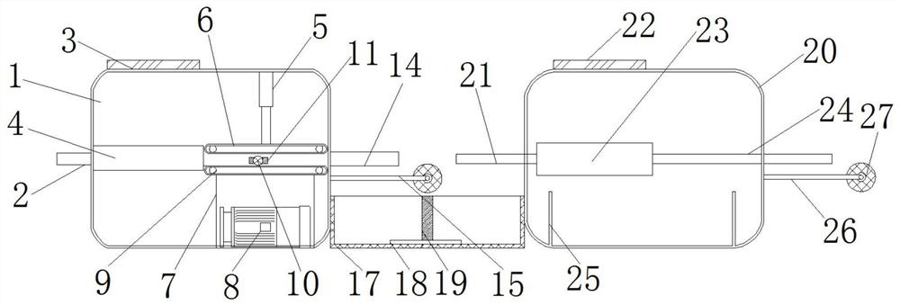
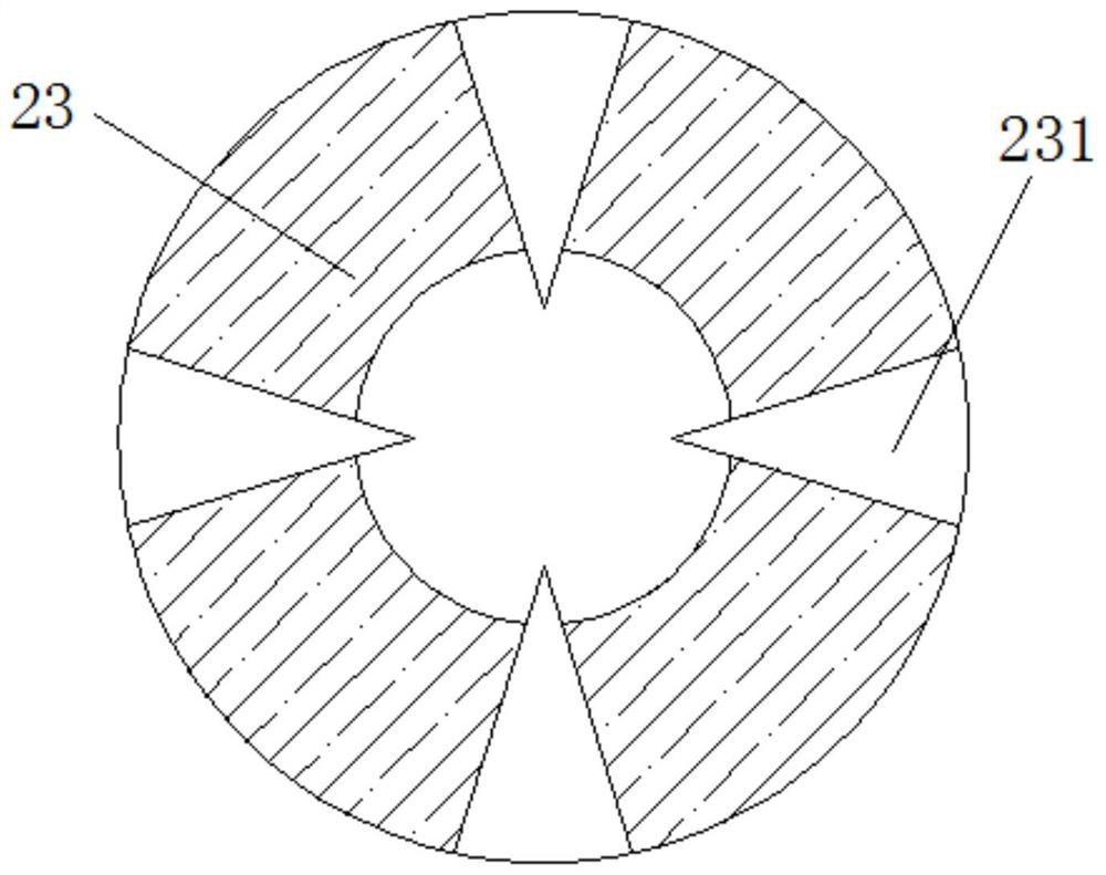
[0026] see Figure 1-9 , a cable installation and stripping mechanism, comprising an outer skin dividing box 1, a first delivery pipeline 2 is fixedly installed on the left side of the outer skin dividing box 1, a first controller 3 is fixedly installed on the top of the outer skin dividing box 1, and the outer skin A shaping device 4 is fixedly installed on the left side of the inner cavity of the partition box 1, a first electric control telescopic rod 5 is ...


PUM


Abstract

The invention provides a cable installation and stripping mechanism, comprising an outer skin dividing box, a first conveying pipe is fixedly installed on the left side of the outer skin dividing box, and a first controller is fixedly installed on the top of the outer skin dividing box, so the A shaping device is fixedly installed on the left side of the inner cavity of the outer skin dividing box, and a first electrically controlled telescopic rod is fixedly installed on the top of the inner cavity of the outer skin dividing box. The cable installation and stripping mechanism, by setting the splitting knife, uses the splitting knife to movably install on the positioning groove, the baffle plate is fixedly installed on the right side of the positioning groove, and the cable moves from left to right, so as to achieve the effect of combining and fixing the splitting knife. The friction between the wire and the splitting knife, the friction between the positioning groove and the splitting knife, and the baffle effectively fix the splitting knife, and it is convenient and convenient to replace it when damaged.

Description

technical field [0001] The invention relates to the technical field of cable recovery equipment, in particular to a cable installation and stripping mechanism. Background technique [0002] With the development of technological networks, there are more and more network devices such as intelligent calls in public life. Because of the application of intelligent network call devices, the national government will install communication equipment in most cities, such as communication cables, circuit signal boxes, signal boxes, etc. Towers, etc., these devices facilitate the communication and application of Internet telephony in daily life. [0003] Various types of communication equipment are mainly connected electrically through cables. Due to accidental factors such as man-made sabotage and natural causes, the cables connected between many devices are damaged. Because of the particularity of the cables, ordinary cables are damaged or long When the cable is seriously damaged, th...

Claims


Application Information

Patent Timeline
Patent Type & Authority Patents(China)
IPC IPC(8): H02G1/12H01B15/00
CPCH02G1/126H01B15/006Y02W30/82
Inventor 肖勇张有为杨永
Owner 湖南金缆电工科技有限责任公司
Learn More