
Emergency rescue vehicle control method and device and emergency rescue vehicle

A control method and emergency rescue technology, applied in the direction of hoisting device, crane, etc., can solve the problems of single function, imperfect professionalism of electrical safety protection system, and inability to meet the spatial characteristics of the working area for various sets of mechanical operations, etc. The effect of working speed and improving efficiency

Active Publication Date: 2021-02-02
JIANGSU XCMG CONSTR MASCH RES INST LTD
View PDF8 Cites 0 Cited by
  • Summary
  • Abstract
  • Description
  • Claims
  • Application Information

AI Technical Summary

Problems solved by technology

[0003] The existing emergency rescue equipment is basically traditional construction machinery and equipment, with a single main function
Under complex rescue conditions, the existing traditional construction machinery equipment needs a variety of sets to complete the operation requirements of the working conditions, and the spatial characteristics of the work area are often unable to meet the mechanical operations of various sets of sets
Even if some equipment has more than two operating functions, it is often divided into main and auxiliary functions, and the operating performance of the auxiliary functions and the professionalism of the electrical safety protection system are not perfect

Method used


Image

  • Emergency rescue vehicle control method and device and emergency rescue vehicle
  • Emergency rescue vehicle control method and device and emergency rescue vehicle
  • Emergency rescue vehicle control method and device and emergency rescue vehicle

Examples


Embodiment Construction

[0047] The present disclosure is described in detail below. In the following paragraphs, different aspects of the embodiments are defined in more detail. Aspects so defined may be combined with any other aspect or aspects unless specifically stated otherwise. In particular, any feature considered to be preferred or advantageous may be combined with one or more other features which are considered to be preferred or advantageous.

[0048] Terms such as "first" and "second" appearing in the present disclosure are only for convenience of description to distinguish different components with the same name, and do not indicate a sequence or a primary and secondary relationship.

[0049] In the description of the present disclosure, the orientations or positional relationships indicated by "up", "down", "left", "right", "front", "rear", "inside" and "outside" are all based on The orientation of the operator sitting in the cab is defined only for the convenience of describing the pre...


PUM


Abstract

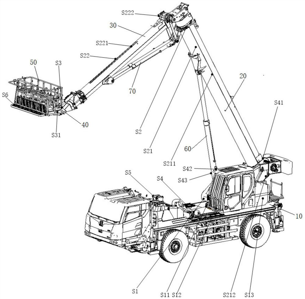
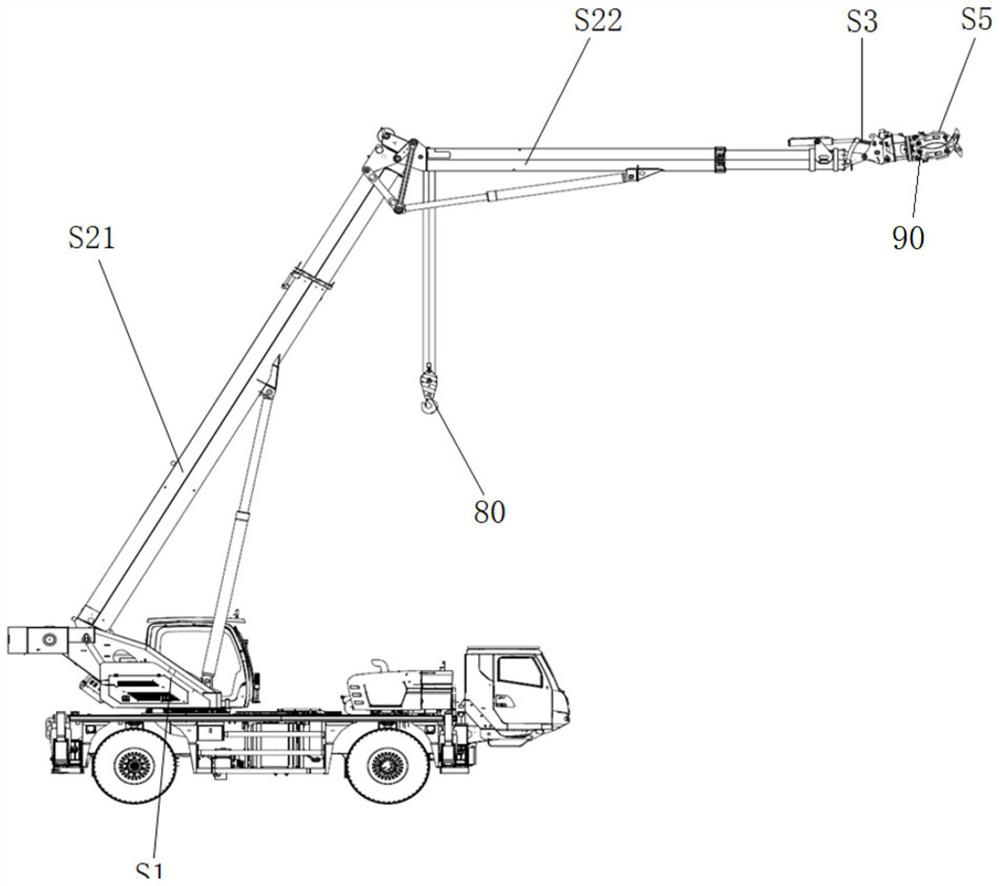
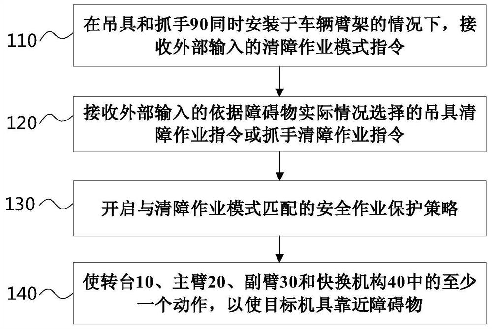
The invention relates to an emergency rescue vehicle control method and device and an emergency rescue vehicle. The emergency rescue vehicle control method comprises the steps: an externally input obstacle clearing operation mode instruction is received under the condition that a lifting appliance and a gripper (90) are installed on the vehicle at the same time; after the obstacle clearing operation mode instruction is received, an externally input lifting appliance obstacle clearing operation instruction or gripper obstacle clearing operation instruction selected according to the actual situation of an obstacle is received, under the lifting appliance obstacle clearing operation instruction, obstacle clearing operation is executed through the lifting appliance installed at the tail end ofa main arm (20), and under the gripper obstacle clearing operation instruction, obstacle clearing operation is executed through the gripper (90) installed at the tail end of an auxiliary arm (30); asafety operation protection strategy matched with an obstacle clearing operation mode is started; at least one of a rotary table (10), the main arm (20), the auxiliary arm (30) and a quick-change mechanism (40) is made to act, so that a target machine tool executing obstacle clearing operation is made to get close to the obstacle.

Description

technical field [0001] The present disclosure relates to the technical field of construction machinery control, in particular to a control method and device for an emergency rescue vehicle and an emergency rescue vehicle. Background technique [0002] For areas where various natural disasters such as earthquakes, landslides, and floods occur, the complexity and particularity of the operating area place extremely stringent requirements on the type and efficiency of rescue vehicle operating tools. It often requires a variety of machines and tools to complete fast and efficient rescue operations in the work area under the professional safety protection system. Therefore, when more than two types of equipment are required for complex rescue conditions, it is necessary to use a suitable electrical control system to improve the utilization efficiency of the boom and minimize the frequency of equipment replacement. [0003] The existing emergency rescue equipment is basically trad...

Claims


Application Information

Patent Timeline
IPC IPC(8): B66F11/04B66C23/42B66C23/16B66C23/62B66C23/68B66C23/84
CPCB66F11/046B66C23/42B66C23/62B66C23/68B66C23/16B66C23/84
Inventor 夏韬张勇李军
Owner JIANGSU XCMG CONSTR MASCH RES INST LTD
Learn More