Efficient and energy-saving municipal drainage system

A municipal drainage system, high-efficiency and energy-saving technology, applied in the direction of waterway system, sewer system, sewage discharge, etc., can solve problems such as waste, achieve the effect of reducing waste and preventing soil loss

Inactive Publication Date: 2021-02-02
宁波汇洲生态建设有限公司
View PDF8 Cites 1 Cited by
  • Summary
  • Abstract
  • Description
  • Claims
  • Application Information

AI Technical Summary

Problems solved by technology

[0005] In view of the related technologies mentioned above, the inventor believes that the rainwater collected by the rainwater harvesting device needs to be pumped away by means of a water pump for secondary treatment when the rainwater collected by the rainwater collection device is recycled, resulting in unnecessary waste

Method used


Image

  • Efficient and energy-saving municipal drainage system
  • Efficient and energy-saving municipal drainage system
  • Efficient and energy-saving municipal drainage system

Examples


Embodiment 1

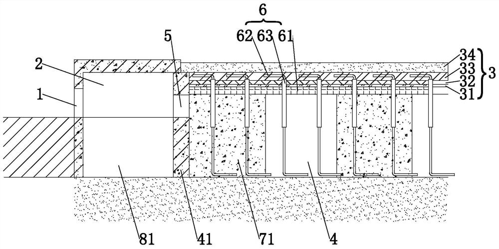
[0040] refer to figure 1 and 2 , the system includes two parts: the road drainage area and the green area drainage area. The green area is set on both sides of the road, that is, the green area drainage area is set on both sides of the road drainage area, and the two are connected.

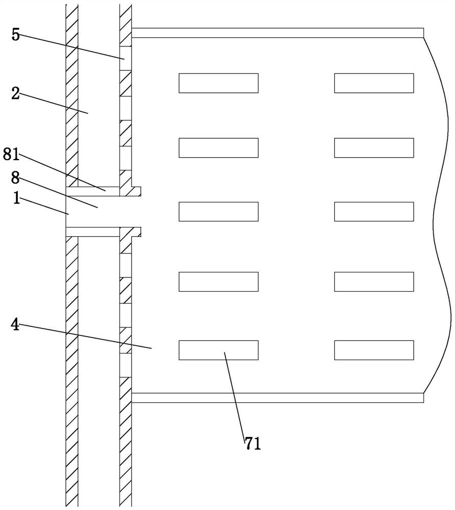
[0041]The road drainage area includes a drainage outlet 1 arranged on the side of the road and a drainage channel 2 arranged at the lower part of the road surface, wherein the drainage outlet 1 is arranged on the side of the sidewalk adjacent to the road, and the drainage channel 2 is arranged under the sidewalk, along the extension of the sidewalk Direction layout. The green drainage area includes the upper surface planting layer 3 and the rainwater collection pool 4 arranged at the lower part of the surface planting layer 3. The surface planting layer 3 is used for planting fibrous root herbs or relatively small flowers.

[0042] The outlet 1 is directly connected to the rainwater collection t...

Embodiment 2

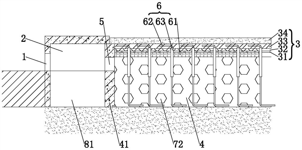
[0051] refer to image 3 The difference between this embodiment and Embodiment 1 is that in this embodiment, the support structure layer is set as a gravel layer 72 laid in the rainwater collection tank 4, and the distance between the bottom of the rainwater collection tank 4 and the support mesh plate 61 is not suitable. Excessively large, be set to 20 centimeters in the present embodiment, the crushed stone grain size in the crushed stone layer 72 remains on 10 centimeters, makes enough gaps be left in the crushed stone layer 72, and the drainage rope 62 is laid in the gap that the crushed stone layer 72 forms middle. The crushed stone layer 72 is used as the support structure layer, which provides more comprehensive support for the surface planting layer 3 and effectively prevents the ground planting layer 3 from collapsing.


PUM


Abstract

The invention relates to the field of municipal energy-saving engineering, in particular to an efficient and energy-saving municipal drainage system. The efficient and energy-saving municipal drainagesystem comprises a road drainage area and a greenbelt drainage area, the road drainage area comprises a drainage port formed in the roadside and a drainage channel formed in the lower portion of a road surface, the greenbelt drainage area comprises an earth surface planting layer and a rainwater collection pool arranged on the lower portion of the earth surface planting layer, the drainage port is connected into the rainwater collection pool, an overflow channel is formed in the side wall of the rainwater collection pool and communicates with the drainage channel, a rainwater drainage mechanism is connected between the earth surface planting layer and the rainwater collection pool, and rainwater in the rainwater collection pool is guided to the earth surface planting layer. According to the system, a municipal drainage system and a garden irrigation system are combined, rainwater drained by municipal administration is used for irrigating and supplementing water to the garden greenbeltfrom bottom to top, rainwater drainage paths and resources consumed by rainwater recycling are reduced, and the purposes of high efficiency and energy conservation are achieved.

Description

technical field [0001] The application relates to the field of municipal energy-saving engineering, in particular to a high-efficiency energy-saving municipal drainage system. Background technique [0002] As we all know, the municipal drainage system is a system dedicated to the discharge and cleaning of road rainwater, domestic sewage and industrial wastewater, and is widely used in municipal work; the existing municipal drainage system includes wastewater concentration pools and sedimentation treatment pools, wastewater concentration pools Centrally collect road rainwater, domestic sewage and industrial wastewater, and carry out sedimentation and purification through the sedimentation treatment tank. [0003] However, in the south and other places, due to the large amount of rainfall, the amount of rainwater discharged into the wastewater concentration pool is also large. Since the rainwater often contains less harmful substances than industrial wastewater, if the rainwat...

Claims


Application Information

Patent Timeline
IPC IPC(8): E03F1/00E03F3/04E03F5/10E01C11/22A01G27/06A01G24/46A01G22/00
CPCA01G27/06A01G22/00A01G24/46E01C11/227E03F1/00E03F3/04E03F5/10E03F5/103E03F5/106Y02A10/30
Inventor 李斌
Owner 宁波汇洲生态建设有限公司
Why Eureka
Try Eureka