
Canal bottom lifting type drainage device for preventing uplift pressure damage of open canal deep excavation section

A drainage device, a lifting technology, applied in water supply devices, sewage removal, drainage structures, etc., can solve problems such as inability to effectively discharge groundwater, high performance requirements for check valves, damage to anti-seepage linings, etc., to ensure drainage efficiency. , to avoid blockage, the effect of not consuming energy and drainage

Active Publication Date: 2021-02-02
UNIV OF JINAN
View PDF5 Cites 0 Cited by
  • Summary
  • Abstract
  • Description
  • Claims
  • Application Information

AI Technical Summary

Problems solved by technology

However, the above-mentioned two technologies have too small displacement, high performance requirements for the check valve, cannot effectively discharge the groundwater when the groundwater level suddenly rises, and cannot effectively reduce the damage to the channel lining caused by the uplift pressure. The key problem is the reverse The check valve is prone to silt at the bottom of the channel or at the foot of the slope, and the check valve cannot be opened when the groundwater needs to be discharged, resulting in damage to the anti-seepage lining of the slope or the bottom of the channel

Method used


Image

  • Canal bottom lifting type drainage device for preventing uplift pressure damage of open canal deep excavation section
  • Canal bottom lifting type drainage device for preventing uplift pressure damage of open canal deep excavation section

Examples


Embodiment 1

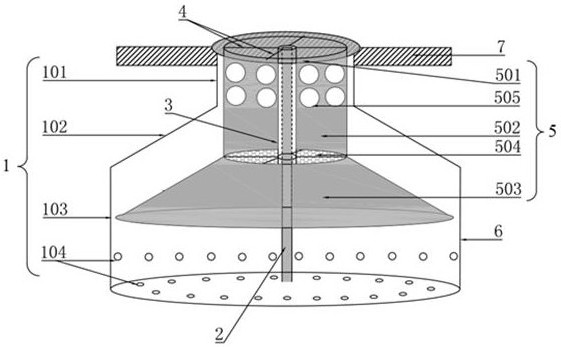
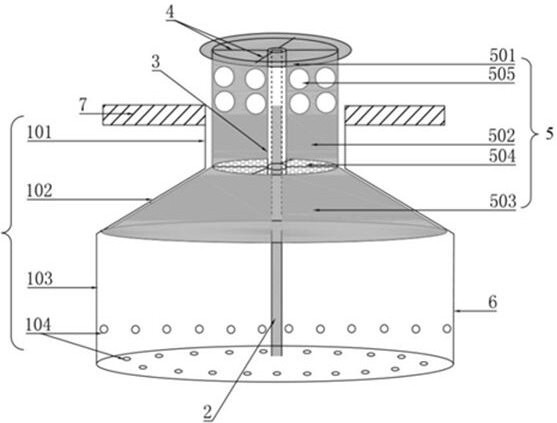
[0029] An elevating drainage device at the bottom of an open channel for deep excavation to prevent damage due to uplift pressure is installed at 7 places at the bottom of the channel, including a water collection tank 1, a lifting mechanism 5 and a guiding mechanism,

[0030] The inside of the water collection tank 1 is a hollow structure for accumulating groundwater. The water collection tank 1 includes an upper part 101, a transition part 102 and a lower part 103 arranged in sequence from top to bottom, forming a convex structure as a whole. The upper part 101 and the lower part 103 are cylindrical structures. The diameter is smaller than the diameter of the lower part, and the transition part 102 is a circular platform structure; the gravel with a particle size larger than the average particle size of the rock and soil at the location is buried around the water collection box 1, and the mesh number of the first filter screen 6 is 60-100 mesh

[0031] The lifting mechanism 5...

Embodiment 2

[0039] A lifting type drainage device at the bottom of an open channel to prevent uplift damage in the deep excavation section, its structural composition is the same as that of Embodiment 1.

[0040] Carry out indoor model test, for water collection tank 1, d 1 =43mm, d 2 =2d 1 , d 3 =D 1 , d 4 =D 2 , where d 1 is the diameter of the bottom surface of the upper part 101, d 2 is the diameter of the bottom surface of the lower part 103, d 3 is the diameter of the upper surface circle of the transition part 102, d 4 is the diameter of the circle on the lower surface of the transition portion 102 . h 1 with l 1 The included angle is 120°, h 1 =20mm, h 2 = h 1 , h 3 =3h 1 , where h 1 is the height of the upper part 101, l 1 is the busbar of the transition part 102, h 2 is the height of the transition part 102, h 3 is the height of the lower part 103 . The lower half of the side of the water collecting tank 1 evenly punches small holes 104, and the bottom surfa...

Embodiment 3

[0045] A lifting type drainage device at the bottom of an open channel to prevent uplift damage in the deep excavation section, its structural composition is the same as that of Embodiment 1.

[0046] Carry out indoor model test, for water collection tank 1, d 1 =43mm, d 2 =2d 1 , d 3 =D 1 , d 4 =D 2 , where d 1 is the diameter of the bottom surface of the upper part 101, d 2 is the diameter of the bottom surface of the lower part 103, d 3 is the diameter of the upper surface circle of the transition part 102, d 4 is the diameter of the circle on the lower surface of the transition portion 102 . h 1 with l 1 The included angle is 120°, h 1 =20mm, h 2 = h 1 , h 3 =2h 1 , where h 1 is the height of the upper part 101, l 1 is the busbar of the transition part 102, h 2 is the height of the transition part 102, h 3 is the height of the lower part 103 . The lower half of the side of the water collecting tank 1 evenly punches small holes 104, and the bottom surfa...


PUM


Abstract

The invention provides a canal bottom lifting type drainage device for preventing uplift pressure damage of an open canal deep excavation section. The canal bottom lifting type drainage device has theremarkable advantages of being free of energy consumption, large in short-time drainage amount, capable of effectively avoiding the problem that the bottom or slope toe of a canal is deposited to block a drainage outlet, free of influence on the water passing capacity of the open canal and the like. The anal bottom lifting type drainage device comprises a water collecting tank, a lifting mechanism and a guide mechanism; the interior of the water collecting tank is of a hollow structure, multiple small holes are formed in the lower half portion and the bottom of the side face, and the part, provided with the small holes, of the water collecting tank is wrapped with a first filter screen; the lifting mechanism comprises a top cover, a column body and a floating plate which are sequentiallyarranged from top to bottom, a plurality of drain holes are formed in the upper part of the column body, and a second filter screen is arranged between the column body and the floating plate; the guide mechanism comprises a guide rail, a sleeve and fixing supports; the guide rail is located in the center of the inner side of the water collecting tank, one end is arranged at the bottom of the watercollecting tank, and the other end extends to the top cover; and the sleeve is fixed to the inner wall of the lifting mechanism through the fixing support, the fixing supports are located on the topcover and the second filter screen, and the sleeve can vertically move along the guide rail along with the lifting mechanism.

Description

technical field [0001] The invention relates to an up-and-down drainage device for the bottom of an open channel to prevent damage from uplift pressure in the deep excavation section. During the process of water delivery in the open channel, the channel is lined with an anti-seepage slope and the bottom of the channel to prevent damage from the uplift pressure of groundwater, which belongs to the process of water delivery in the open channel. Anti-clogging and pressure-reducing drainage technical field. Background technique [0002] The distribution of water resources in various parts of China is uneven. In order to solve the contradiction between supply and demand of water resources, the country has built water diversion projects. Among them, channel lining water delivery is widely used because of its low cost and good water delivery effect. However, for some high-lying places, deep excavation of square sections is often used to ensure the self-flow of canal water, and deep...

Claims


Application Information

Patent Timeline
Patent Type & Authority Applications(China)
IPC IPC(8): E03F1/00E03F5/14
CPCE03F1/00E03F5/14
Inventor 王维平孙秀秀王兵孙佑光李文良赵伟东曲士松
Owner UNIV OF JINAN
Learn More