Fabricated concrete member box-shaped sleeve type connecting structure, construction method and application

A technology for connecting structures and concrete, applied in building components, building structures, walls, etc., can solve the problems of safety threats, high construction requirements, and slurry fallback of prefabricated concrete frame structures, so as to meet the requirements of structural integrity, Convenience in construction and avoidance of steel bar collision

Inactive Publication Date: 2021-02-02
SHANGHAI RES INST OF BUILDING SCI CO LTD +1
View PDF10 Cites 0 Cited by
  • Summary
  • Abstract
  • Description
  • Claims
  • Application Information

AI Technical Summary

Problems solved by technology

At present, the connection between the stressed steel bars of precast concrete members generally adopts sleeve grouting connection, grout anchor lap connection, etc., but this connection method has high requirements for construction, and grouting such as grout fallback and grout leakage are prone to occur in actual projects Not full
However, the mechanical performance of precast concrete components is more sensitive to grouting defects, which poses a great threat to the safety of prefabricated concrete frame structures.

Method used


Image

  • Fabricated concrete member box-shaped sleeve type connecting structure, construction method and application
  • Fabricated concrete member box-shaped sleeve type connecting structure, construction method and application
  • Fabricated concrete member box-shaped sleeve type connecting structure, construction method and application

Examples


Embodiment 1

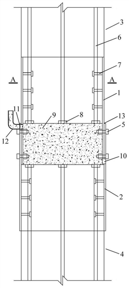
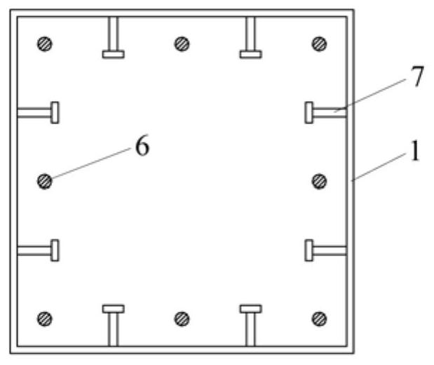
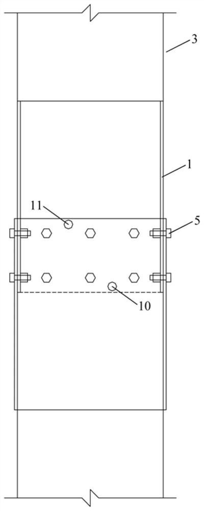
[0041] to combine Figure 1 to Figure 5 , Embodiment 1 provides a prefabricated concrete column box-shaped steel sleeve connection structure, including an upper precast concrete column 3, a lower precast concrete column 4, an upper precast concrete column box-shaped steel sleeve 1, a lower precast concrete column box Shaped steel sleeve 2, unilateral bolt 5, thin steel plate 13, longitudinal reinforcement 6, anchor plate 8, peg 7 and grouting material 9.

[0042] The box-shaped steel sleeve (that is, the upper precast concrete column box-shaped steel sleeve 1 in the figure and the lower precast concrete column box-shaped steel sleeve 2) and the precast concrete column (that is, the upper precast concrete column 3 in the figure and the lower precast concrete column Column 4) The inner surface of the concrete joint part should be welded with stud 7.

[0043]Bolt holes should be reserved for the part of the upper precast concrete column box-shaped steel sleeve 1 or the lower pre...

Embodiment 2

[0056] combine Figure 6 ~ Figure 8 , Embodiment 2 provides an assembled concrete shear wall box-shaped steel sleeve connection structure, including an upper precast concrete shear wall 23, a lower precast concrete shear wall 24, and an upper precast concrete shear wall box-shaped steel sleeve Tube 21, lower prefabricated concrete shear wall box-shaped steel sleeve 22, unilateral bolt 25, thin steel plate for plug joint 33, longitudinal reinforcement 26, anchor plate 28, stud 27 and grouting material 29.

[0057] The box-shaped steel sleeve (that is, the upper precast concrete shear wall box steel sleeve 21 in the figure and the lower precast concrete shear wall box steel sleeve 22) and the precast concrete shear wall (that is, the upper precast concrete shear wall in the figure) The inner surface of the concrete joint part of the shear wall 23 and the lower prefabricated concrete shear wall 24) should be welded with studs 27.

[0058] Bolt holes should be reserved for the pa...

Embodiment 3

[0071] combine Figure 9 ~ Figure 11 , this embodiment provides an assembled concrete beam box-shaped steel sleeve connection structure, including a right precast concrete beam 43, a left precast concrete beam 44, a right precast concrete beam box steel sleeve 41, a left side Prefabricated concrete beam box-shaped steel sleeve 42, unilateral bolt 45, thin steel plate 53, longitudinal reinforcement 46, anchor plate 48, stud 47 and grouting material 49.

[0072] The inner surface of the right side precast concrete beam box steel sleeve 41 or the left side precast concrete beam box steel sleeve 42 and the right side precast concrete beam 43 or the left side precast concrete beam 44 concrete joint part should be welded with studs 47 .

[0073] Bolt holes should be reserved for the parts of the box-shaped steel sleeves (numbers 41 and 42 in the figure) that are not in contact with the concrete of the precast concrete beams (numbers 43 and 44 in the figure).

[0074] A grouting hol...


PUM


Abstract

The invention discloses a fabricated concrete member box-shaped sleeve type connecting structure, a construction method and application. The structure comprises a first barrel-shaped body and a secondbarrel-shaped body, wherein a cavity of the first barrel-shaped body is divided into a first area and a second area, and a cavity of the second barrel-shaped body is divided into a third area and a fourth area; first studs and second studs are distributed on the inner wall of a first-area barrel body and the inner wall of a fourth-area barrel body correspondingly; the barrel body of the first barrel-shaped body is inserted into a barrel body corresponding to the third area, and then the barrel body of the first barrel-shaped body and the barrel body of the third area are nested into a whole and fastened; a nested area is used as a grouting area, and a grouting hole and a grout outlet hole which communicate with the outside are formed in the barrel wall of the grouting area; the fabricatedconcrete member box-shaped sleeve type connecting structure further comprises a prefabricated first concrete member unit which starts from the first and second area boundary and is partially wrappedby the first area cavity, and a prefabricated second concrete member unit which starts from the third and fourth area boundary and is partially wrapped by the fourth area cavity, the first studs and first ribs are embedded inside the prefabricated first concrete member unit, and the second studs and second ribs are embedded inside the prefabricated second concrete member unit; and the plurality offirst ribs and the plurality of second ribs form rib groups parallel to the corresponding the barrel-shaped bodies respectively.

Description

technical field [0001] The invention belongs to the technical field of civil engineering prefabricated buildings, and in particular relates to a box-shaped sleeve connection structure of prefabricated concrete components and its construction method and application. Background technique [0002] Prefabricated concrete structures have been widely used in practical projects due to their advantages of fast construction speed, flexible structural layout, low cost, and environmental protection. The connection structure between prefabricated components plays a vital role in the safety of the overall structure. At present, the connection between the stressed steel bars of precast concrete members generally adopts sleeve grouting connection, grout anchor lap connection, etc., but this connection method has high requirements for construction, and grouting such as grout fallback and grout leakage are prone to occur in actual projects The case of not being full. The mechanical perform...

Claims


Application Information

Patent Timeline
Patent Type & Authority Applications(China)
IPC IPC(8): E04B1/21E04B2/60E04B2/68
CPCE04B1/21E04B1/215E04B2/60E04B2/68
Inventor 李向民肖顺许清风王卓琳高润东张富文
Owner SHANGHAI RES INST OF BUILDING SCI CO LTD
Why Eureka
Try Eureka