a reciprocating pump

A technology of reciprocating pumps and crankshafts and connecting rods, applied in the field of reciprocating pumps, can solve the problems of large water tank occupation and achieve the effects of reducing energy waste, improving cooling effect, and improving flow capacity

Active Publication Date: 2022-07-01
NINGBO QIANHU PETROLEUM EQUIP
View PDF6 Cites 0 Cited by
  • Summary
  • Abstract
  • Description
  • Claims
  • Application Information

AI Technical Summary

Problems solved by technology

[0006] In order to solve the problem that the existing reciprocating pump uses lubricating oil circulation to cool down, it is necessary to install a water tank, and the water tank occupies too much space. This application provides a reciprocating pump

Method used


Image

  • a reciprocating pump
  • a reciprocating pump
  • a reciprocating pump

Examples


Embodiment Construction

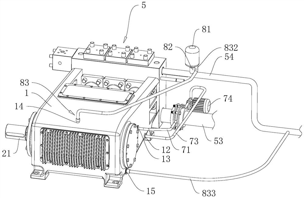
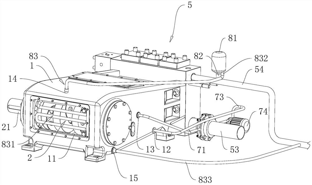
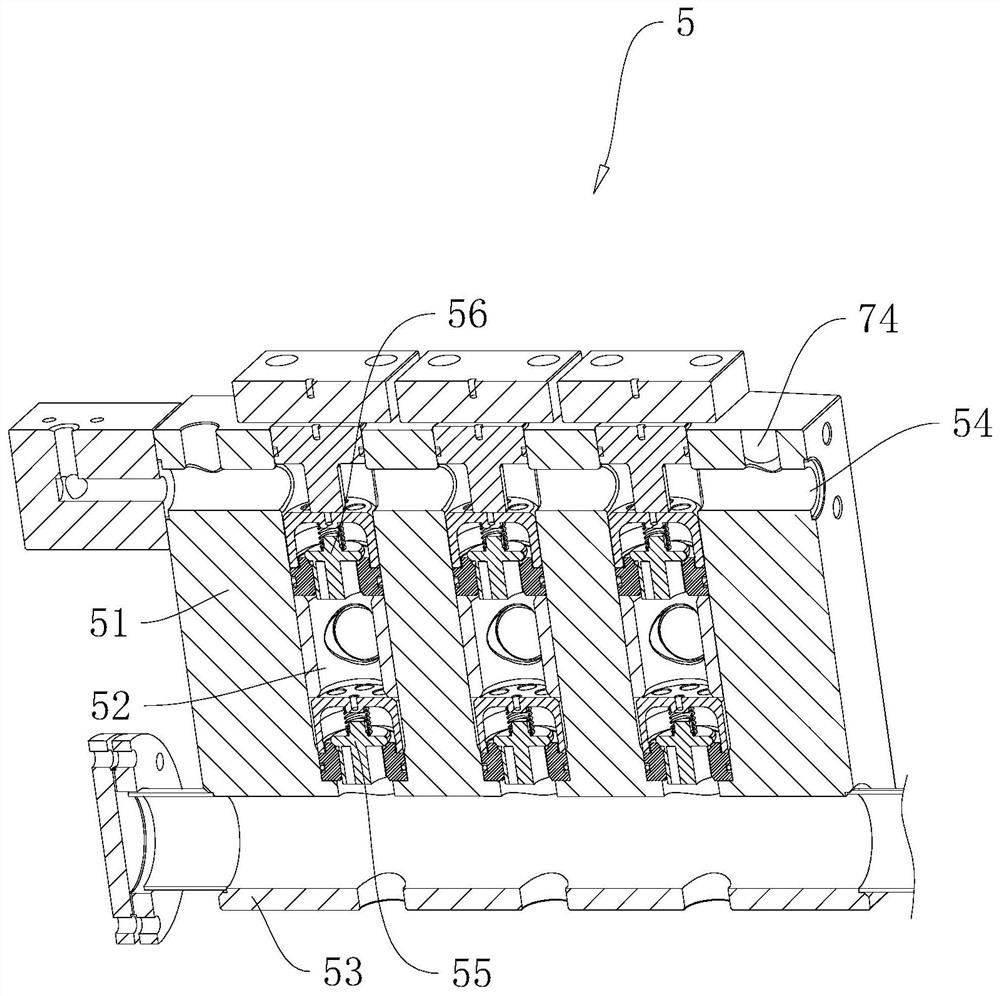
[0040] Attached to the following Figure 1-7 This application will be described in further detail.

[0041] The embodiment of the present application discloses a reciprocating pump. refer to figure 1 and figure 2 , a reciprocating pump, including a casing 1, a crankshaft connecting rod mechanism 2, a plunger, a cylinder liner assembly and a suction and discharge valve group 5 arranged in the casing 1. The casing 1 is provided with a power chamber 11, and the crankshaft connecting rod mechanism 2 And the plunger is installed in the power chamber 11 . There are three crankshaft connecting rod mechanisms 2, and the three crankshaft connecting rod mechanisms 2 are driven by the same crankshaft 21; the crankshaft 21 is provided with three connecting rod journals, and the three connecting rod journals are arranged along the axis of the crankshaft 21 at intervals, so that the three crankshaft connecting rods are The mechanism 2 performs reciprocating motion in sequence, and the ...


PUM


Abstract

The application relates to a reciprocating pump, which belongs to the technical field of hydraulic pumps. It includes a casing, a valve body and a cooling assembly, the valve body is provided with a liquid discharge pipeline, the casing is provided with a power chamber, the casing is provided with a liquid inlet and a liquid outlet that communicate with the power chamber, and the cooling assembly includes a heat sink. Oil pipe, cooling part, cold oil pipe and circulating pump. One end of the hot oil pipe is connected with the liquid outlet, the other end of the hot oil pipe is connected with the cooling element, one end of the cold oil pipe is connected with the liquid inlet, the other end of the cold oil pipe is connected with the cooling element, and the drain pipe The method of connecting the suction pipe for absorbing liquid on the road, the cooling part includes a clamping part and a heat dissipation part, the clamping part is annular and the inner hollow is clamped to the flange plate and the suction pipe of the drainage pipeline. Between the blue and the plate, the radiating part includes at least one radiating pipe. Both ends of the radiating pipe are fixed to the inner ring of the clamping part and communicate with the clamping part. The present application has the advantage of not requiring a separate water tank.

Description

technical field [0001] The present application relates to the technical field of hydraulic pumps, and in particular, to a reciprocating pump. Background technique [0002] The current reciprocating pump includes a crankshaft connecting rod mechanism, a plunger driven by the crankshaft connecting rod mechanism, a cylinder liner assembly matched with the plunger, and a suction and discharge valve group. The suction and discharge valve group includes a valve body and a suction liquid disposed in the valve body. Check valve and discharge check valve. The valve body is provided with a suction pipeline, a power chamber and a discharge pipeline which are connected in sequence. The cylinder liner assembly is arranged on the valve body and communicated with the power chamber. The suction check valve is provided with Between the power chamber and the liquid suction pipeline, a liquid discharge check valve is arranged between the power chamber and the liquid discharge pipeline. The mo...

Claims


Application Information

Patent Timeline
Patent Type & Authority Patents(China)
IPC IPC(8): F04B1/00F04B53/08F04B53/18F04B53/16F04B11/00
CPCF04B1/00F04B53/08F04B53/18F04B53/16F04B11/0091
Inventor 郑上军汪耀华郝飞刘梦然
Owner NINGBO QIANHU PETROLEUM EQUIP
Why Eureka
Try Eureka