
Suspension force model prediction control system of bearingless coreless permanent magnet motor

A model predictive control, permanent magnet motor technology, applied in the control system, vector control system, motor generator control and other directions, can solve the problems of large amount of calculation, poor accuracy, etc., to avoid flux linkage ripple, solve the problem of insufficient accuracy, Solve the complex effects of parameter tuning

Inactive Publication Date: 2021-02-02
JIANGSU UNIV
View PDF5 Cites 1 Cited by
  • Summary
  • Abstract
  • Description
  • Claims
  • Application Information

AI Technical Summary

Problems solved by technology

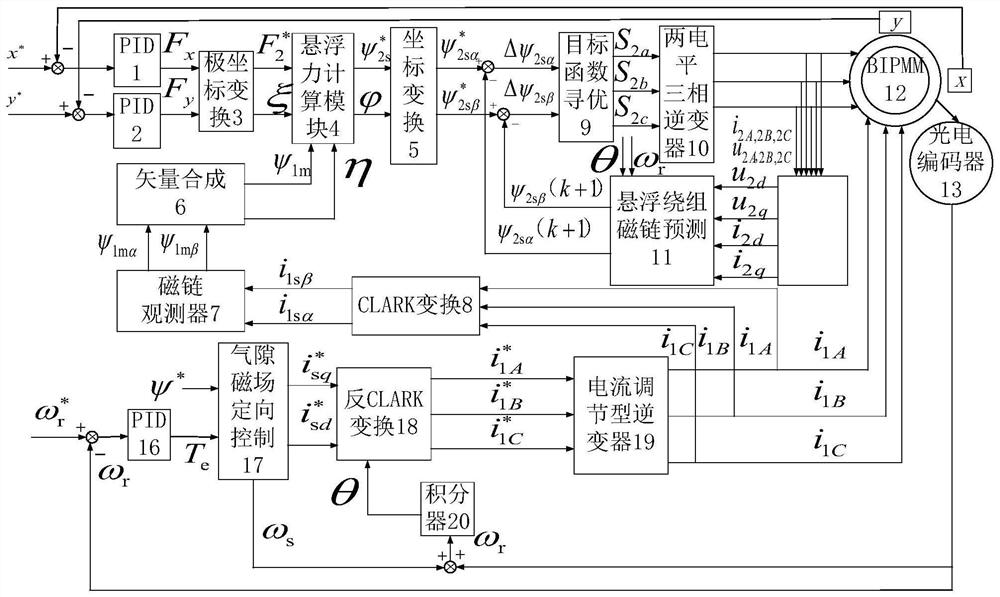
[0003] The purpose of the present invention is to solve the problems of poor accuracy and large amount of calculation in the suspension force control of bearingless ironless permanent magnet motors, and propose a new bearingless ironless permanent magnet motor suspension force model prediction control system, which reduces the The extension of control time caused by system sampling and digital calculation delay improves the accuracy of suspension force control

Method used


Image

  • Suspension force model prediction control system of bearingless coreless permanent magnet motor
  • Suspension force model prediction control system of bearingless coreless permanent magnet motor
  • Suspension force model prediction control system of bearingless coreless permanent magnet motor

Examples


Embodiment Construction

[0012] Such as figure 1 Shown, the present invention is made up of suspension force control part and rotational speed control part.

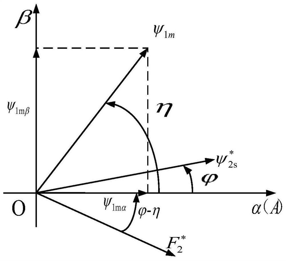
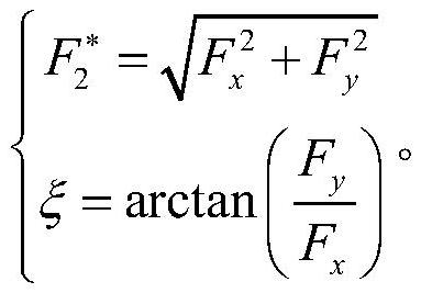
[0013] Suspension force control part: including two PID controllers 1, 2 and polar coordinate transformation module 3 connected in series, suspension force calculation module 4, first coordinate transformation module 5, objective function optimization module 9, two-level three The phase inverter 10, the second coordinate transformation module 21 and the suspension winding flux linkage prediction module 11 also include a CLARK transformation module 8, a flux linkage observer module 7 and a vector synthesis module 6 connected in series. Among them, the input of the CLARK transformation module 8 is the three-phase current i of the torque winding of the bearingless coreless permanent magnet motor 12 1A i 1B i 1C , the output end of the vector synthesis module 6 is connected to the input end of the suspension force calculation module 4 . The inpu...


PUM


Abstract

The invention discloses a suspension force model prediction control system of a bearingless coreless permanent magnet motor. According to the invention, a suspension force control part comprises two PID controllers, further comprises a polar coordinate conversion module, a suspension force calculation module, a first coordinate transformation module, an objective function optimization module, a two-level three-phase inverter, a second coordinate transformation module and a suspension winding flux linkage prediction module which are sequentially connected in series, and also comprises a CLARK transformation module, a flux linkage observer module and a vector synthesis module which are sequentially connected in series. A rotating speed control part comprises a photoelectric encoder and an integrator, and further comprises a third PID controller, an air-gap magnetic field orientation control module, an inverse CLARK transformation module and a current regulation type inverter which are sequentially connected in series. According to the invention, suspension force winding flux linkage corresponding to each switching state in a next sampling period is predicted through initially observed torque winding flux linkage; and a voltage vector of the optimal switching state is selected by utilizing a value function and input into the next control period, so the suspension force are simultaneously controlled and optimized.

Description

technical field [0001] The invention belongs to the field of bearingless motor control, and relates to a multivariable, non-linear, strong coupling direct control technology of the suspension force of a bearingless coreless permanent magnet motor. Background technique [0002] Bearingless coreless permanent magnet motor is a new type of motor that combines the characteristics of ironless permanent magnet motor and magnetic bearing. It not only has the advantages of high efficiency, strong overload capacity, no cogging torque and low rotor loss, but also has the advantages of magnetic Bearings do not require lubrication, friction and maintenance, and can achieve high-speed or ultra-high-speed operation. They have application prospects in the fields of chemical engineering, life sciences, energy transportation, aerospace and robotics. However, since the bearingless coreless permanent magnet motor itself is a multivariable, nonlinear, and strongly coupled controlled object, it ...

Claims


Application Information

Patent Timeline
Patent Type & Authority Applications(China)
IPC IPC(8): H02P21/00
CPCH02P21/0003
Inventor 朱熀秋张子辰刁小燕潘伟
Owner JIANGSU UNIV
Learn More