
Interferometer and method for producing an interferometer

An interferometer and component technology, which is applied in the field of interferometers and used in the manufacture of interferometers to achieve the effect of reducing the risk of occlusion and improving transmittance

Pending Publication Date: 2021-02-02
ROBERT BOSCH GMBH
View PDF6 Cites 1 Cited by
  • Summary
  • Abstract
  • Description
  • Claims
  • Application Information

AI Technical Summary

Problems solved by technology

[0006] In summary, the prior art thus only allows a structural element architecture for which the maximum transmission wavelength is predetermined by a process control fix as a function of the initial mirror spacing at rest and the minimum transmission wavelength is determined by an electrostatic bite to limit

Method used


Image

  • Interferometer and method for producing an interferometer
  • Interferometer and method for producing an interferometer
  • Interferometer and method for producing an interferometer

Examples


Embodiment Construction

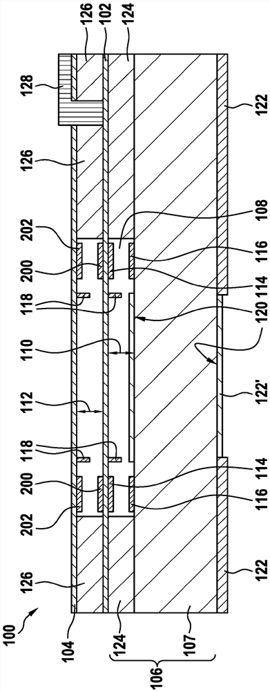
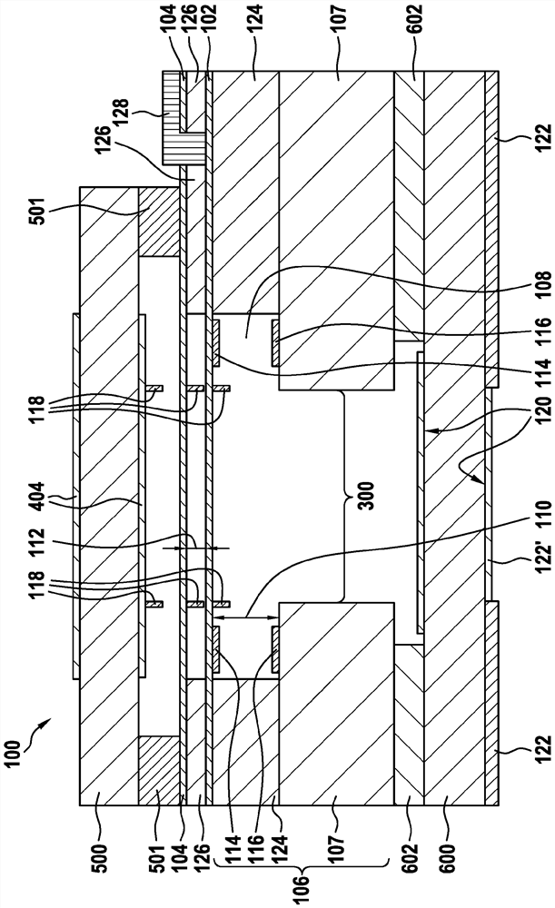
[0048] figure 1 A schematic diagram of an interferometer 100 according to an exemplary embodiment is shown. Interferometer 100 comprises a first mirror element 102 and a second mirror element 104 arranged opposite first mirror element 102 with a variable mirror pitch. The first mirror element 102 , here for example the lower mirror, is arranged on the holding element 106 opposite the actuating recess 108 of the holding element 106 and delimits an actuating gap 110 therewith, wherein the The holding element is based here by way of example on a base body (wafer) 107 and additional layers which will be described in more detail below. A cross-section of a Fabry-Perot interferometer is shown as an example, for which the actuation takes place electrostatically via the actuation slit 110, wherein the actuation The initial pitch of the slots 110 can be adjusted independently of the mirror pitch. The second mirror element 104 , here for example the upper mirror, defines an optical g...


PUM


Abstract

The invention relates to an interferometer (100) consisting of a holding element (106) having an actuation recess (108), a first mirror element (102), which is or can be arranged on the holding element (106) opposite the actuation recess (108), and a second mirror element (104), which is or can be arranged opposite the first mirror element (102) at a mirror distance, to form an optical slit (112),wherein the first mirror element (102) is or can be arranged between the second mirror element (104) and the holding element (106) and the optical slit (112) is spatially separated from the actuationrecess (108) by the first mirror element (102). The interferometer (100) further comprises an electrode pair of a first actuation electrode (114), which is defined, arranged and / or can be arranged onor in one of the mirror elements (102) or (104), and of a second actuation electrode (116), which is defined, arranged and / or can be arranged on a side of the actuation recess (108) opposite the first actuation electrode (114). The mirror distance can be varied by applying an electrical voltage to the electrode pair.

Description

technical field [0001] The invention relates to a device or a method of the type according to the independent claims. A computer program is also the subject of the invention. Background technique [0002] Tunable spectral filters with the possibility of miniaturization can be realized by means of MEMS technology, for example as Fabry-Perot interferometers. Use is made here of the fact that a cavity formed by two plane-parallel, highly reflective mirror surfaces at a mutual distance exhibits a high degree of transmission in the optical wavelength range only for wavelengths for which In other words, the cavity length corresponds to multiple integer multiples of half the wavelength. The distance, which is also referred to as the cavity length, can be varied, for example, by means of electrostatic or piezoelectric actuation, resulting in a spectrally tunable filter element. A crucial influencing factor for the performance of such spectrometers is the parallelism or plane para...

Claims


Application Information

Patent Timeline
Patent Type & Authority Applications(China)
IPC IPC(8): G01J3/26G01J5/02G02B26/00G01J3/02
CPCG01J3/027G01J3/0291G01J3/26G01J5/0235G02B26/001G01J3/021G01J3/0237G01J2003/1247
Inventor R·诺特梅耶C·胡博尔R·罗德尔B·斯坦C·谢林C·D·克莱默
Owner ROBERT BOSCH GMBH
Learn More