Control method of integrated interferometer

A control method and interferometer technology, which is applied in the field of integrated circuit equipment manufacturing, can solve the problems of X-direction position deviation and measurement axis installation error, etc., and achieve the effect of reducing the impact

Pending Publication Date: 2016-07-27
SHANGHAI MICRO ELECTRONICS EQUIP (GRP) CO LTD
View PDF4 Cites 0 Cited by
  • Summary
  • Abstract
  • Description
  • Claims
  • Application Information

AI Technical Summary

Problems solved by technology

However, in actual situations, when there is an installation error in the X-direction interferometer, and the installation error of each measurement axis is different, the X-direction position of the table measured by different X-direction interferometers will also have deviations

Method used


Image

  • Control method of integrated interferometer
  • Control method of integrated interferometer
  • Control method of integrated interferometer

Examples


Embodiment approach

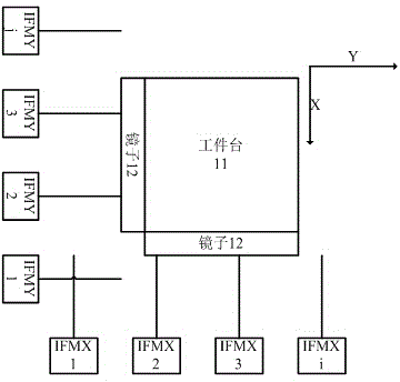
[0036] Single interferometer control scheme, on the travel of the workpiece table / mask table, different areas are controlled by different interferometers, and the switching of the two interferometers is completed at the intersection of the two interferometer control areas, such as Image 6 As shown, for the measurement system composed of three interferometers, the weight is 1 in the area controlled by each interferometer, and the weight is 0 in other areas.

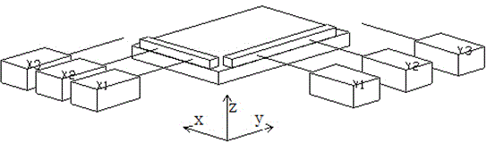
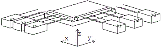
[0037] Consider the scheme of switching between two interferometers, set a switching area in the common control area of ​​the two interferometers, in this area, assign the weight factors of the two interferometers in the form of multi-order functions, and finally get the stage position is calculated by weighting the measured values ​​of the two interferometers, such as Figure 7 As shown in the example, when located in the switching region, the weight factor of one interferometer gradually decreases from 1 to 0, and the w...


PUM


Abstract

The invention discloses a control method for an integrated interferometer device, which is characterized in that it includes: step 1, setting at least two interferometers in the first direction; step 2, setting the control weight of each interferometer, wherein the control weight distribution As follows: when the workpiece table or mask table moves to the control area of ​​each interferometer, the weight factor is equal to 1; when the workpiece table or mask table moves to the non-control area, the weight factor is equal to 0; when the workpiece table or mask table moves Move to the common control area of ​​the two interferometers, and its weight factor is a multi-order function; step 3, judge whether any interferometer loses light, and if the judgment result is true, dynamically reset the lost interferometer to zero.

Description

technical field [0001] The invention relates to the field of integrated circuit equipment manufacturing, in particular to an integrated interferometer device and a control method. Background technique [0002] The high-precision motion positioning of the workpiece table of the lithography equipment is realized by the interferometer (IFM). The interferometer is composed of a laser transmitter, a signal receiver and a mirror. With the increase of the Y-direction travel of the table, the length of the X-direction reflector of the table is also required to increase. However, due to processing difficulties and precision issues, the length of the reflector will be limited. In the case that the Y-direction travel of the table is greater than the length of the X-direction mirror without increasing the length of the mirror, the X-direction interferometer measurement axes can be arranged at different Y-direction positions, that is, during the Y-direction movement of the table, respe...

Claims


Application Information

Patent Timeline
Patent Type & Authority Applications(China)
IPC IPC(8): G03F7/20
Inventor 沈鑫
Owner SHANGHAI MICRO ELECTRONICS EQUIP (GRP) CO LTD
Why Eureka
Try Eureka