Energy-saving machining equipment with speed regulation function for metal cutting

A technology for metal cutting and processing equipment, applied in metal processing equipment, metal processing mechanical parts, measuring/indicating equipment, etc., can solve problems affecting equipment processing accuracy, affecting production efficiency, affecting processing time, etc. Empty tool time, improve cutting efficiency, and ensure the effect of accuracy

Inactive Publication Date: 2021-02-05
李后俊
View PDF0 Cites 0 Cited by
  • Summary
  • Abstract
  • Description
  • Claims
  • Application Information

AI Technical Summary

Problems solved by technology

[0003] However, when the existing metal processing equipment works in the automatic operation mode, the cutting feed rate remains constant according to the given parameters, so that when the equipment is idling, the speed remains unchanged, thereby affecting the processing time and production efficiency. , Moreover, when there is a problem with the rotating shaft of the equipment, the cutting angle may be shifted, which may affect the processing accuracy of the equipment; therefore, those skilled in the art provide an energy-saving processing equipment for metal cutting with speed regulation , to solve the problems raised in the above background technology

Method used


Image

  • Energy-saving machining equipment with speed regulation function for metal cutting
  • Energy-saving machining equipment with speed regulation function for metal cutting
  • Energy-saving machining equipment with speed regulation function for metal cutting

Examples


Embodiment Construction

[0021] The following will clearly and completely describe the technical solutions in the embodiments of the present invention with reference to the accompanying drawings in the embodiments of the present invention. Obviously, the described embodiments are only some, not all, embodiments of the present invention. Based on the embodiments of the present invention, all other embodiments obtained by persons of ordinary skill in the art without making creative efforts belong to the protection scope of the present invention.

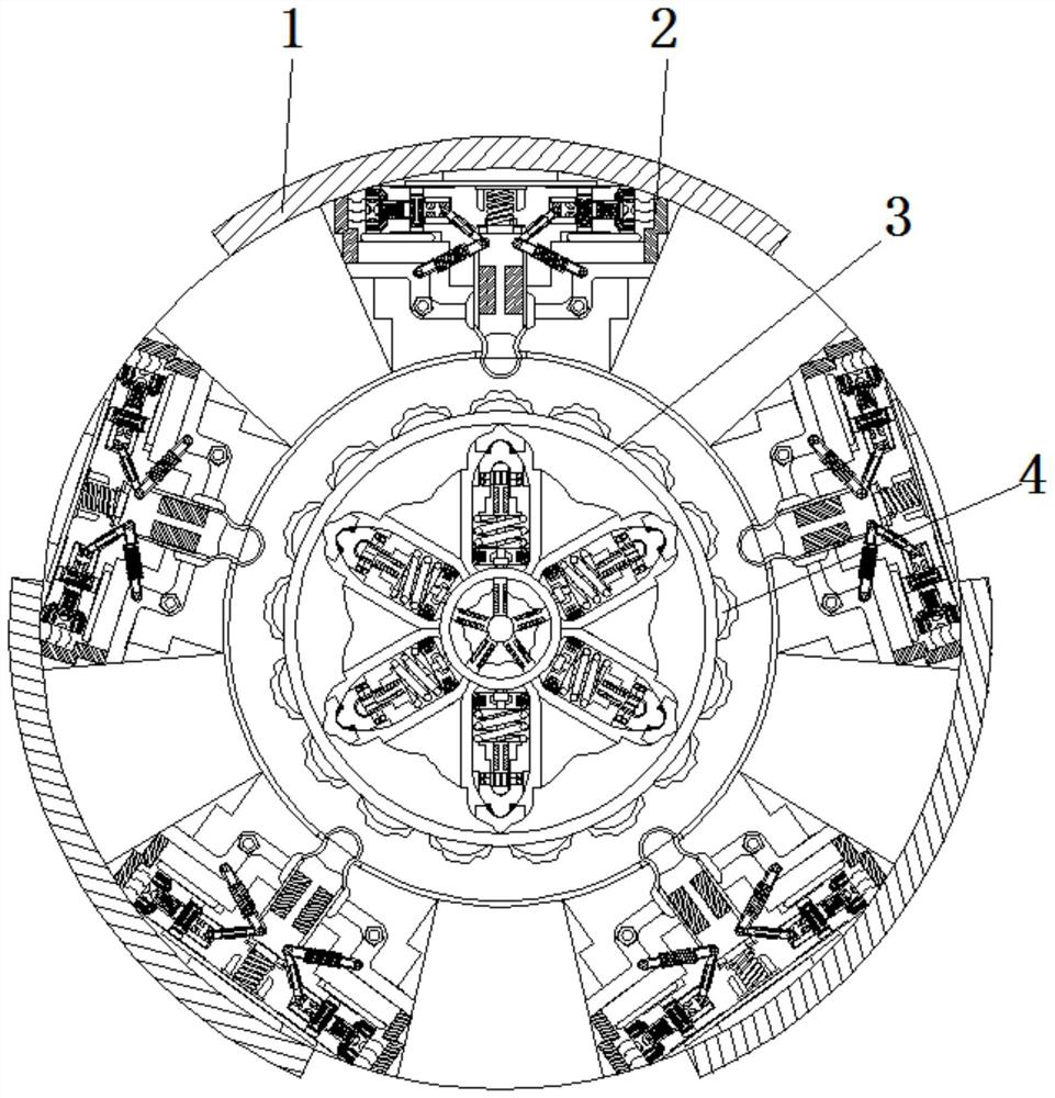
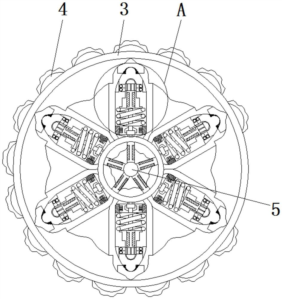
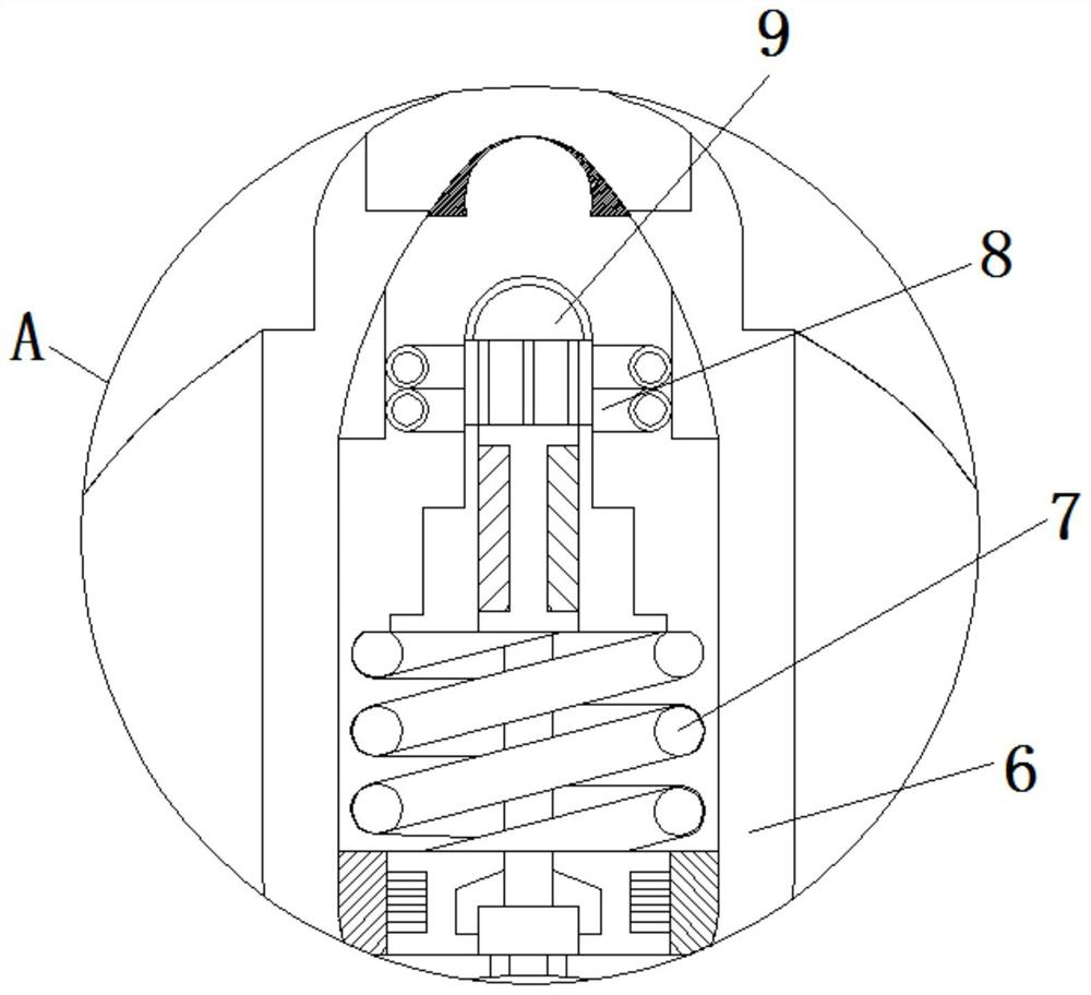
[0022] see Figure 1-5 , an energy-saving processing equipment used for metal cutting with a speed regulating function, comprising a main body 1, the inner wall of the main body 1 is fixedly connected with a fixing frame 2, the inside of the fixing frame 2 is a cavity, and the inside of the fixing frame 2 is opened There is a chute that matches with the extrusion head 10. The center shaft 3 is plugged into the interior of the equipment main body 1. The outer s...


PUM


Abstract

The invention relates to the technical field of metal cutting machining equipment, in particular to energy-saving machining equipment with a speed regulation function for metal cutting. The energy-saving machining equipment comprises an equipment body, a fixing frame is fixedly connected to the inner wall of the equipment body, a central shaft is inserted into the equipment body, a convex block isfixedly connected to the outer surface of the central shaft, a driving shaft is inserted into the center of the inner part of the center shaft, and a positioning frame is fixedly connected to the position, located on the outer side of the driving shaft, of the inner part of the center shaft. When hollow feeding is conducted in a machining process of the equipment, the feeding cutting speed of hollow feeding is automatically changed, and the purposes of shortening the hollow feeding time and improving the cutting machining efficiency of a numerical control machine tool are achieved. By enabling a signal lamp to flicker back and forth, the purpose of reminding workers is achieved, so that the workers are reminded to maintain the rotating shaft of the equipment in time, meanwhile, the working accuracy of the equipment can be well guaranteed, and therefore the detection effect can be well achieved.

Description

technical field [0001] The invention relates to the technical field of metal cutting processing equipment, in particular to energy-saving processing equipment for metal cutting with a speed regulating function. Background technique [0002] Metal is a kind of material with luster, that is, strong reflection of visible light, high ductility, easy conduction, heat conduction and other properties. Metal cutting is a method of material removal and forming in metal forming process, which still occupies a large part in today's mechanical manufacturing. Proportion. The metal cutting process is a process in which the workpiece and the tool interact. [0003] However, when the existing metal processing equipment works in the automatic operation mode, the cutting feed rate remains constant according to the given parameters, so that when the equipment is idling, the speed remains unchanged, thereby affecting the processing time and production efficiency , Moreover, when there is a pr...

Claims


Application Information

Patent Timeline
Patent Type & Authority Applications(China)
IPC IPC(8): B23D79/00B23Q3/00B23Q17/24
CPCB23D79/00B23Q3/00B23Q17/24
Inventor 李后俊
Owner 李后俊
Why Eureka
Try Eureka