
Compound numerically-controlled gantry machine

A compound machine and gantry technology, applied in the field of CNC machine tools, can solve the problems of high processing cost, unrealistic processing, cumbersome processing steps, etc.

Pending Publication Date: 2021-02-05
泉州市创佳自动化设备有限公司
View PDF0 Cites 0 Cited by
  • Summary
  • Abstract
  • Description
  • Claims
  • Application Information

AI Technical Summary

Problems solved by technology

In the prior art, machining centers are divided into vertical, horizontal and gantry crane machining centers, all of which are equipped with a main shaft, so only one-sided machining can be realized. Then process the other side of the workpiece, so that it is impossible to process both sides of the workpiece at the same time, and the processing efficiency is low
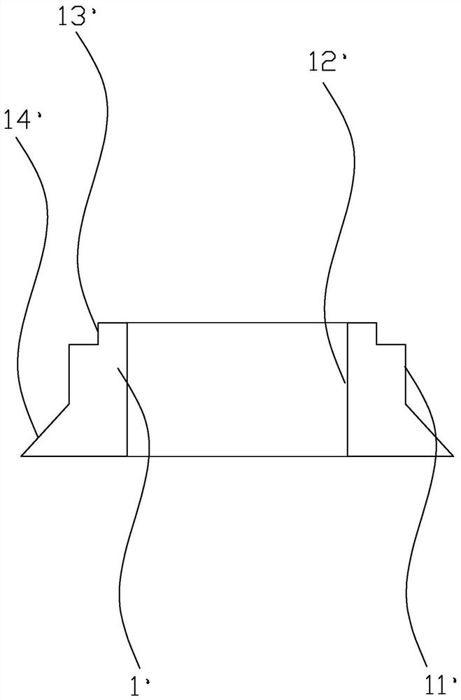
refer to figure 1 , especially for the processing of the large circular knitting machine saddle 1', it is necessary to process the outer circumference 11' of the saddle 1', the inner circumference inner side 12' of the inner ring, the upper end surface 13' and the lower inclined annulus 14' outside the circumference, It often requires multiple processing centers to cooperate with the processing, the processing efficiency is low, and the processing steps are cumbersome. At the same time, the saddle of the large circular machine is heavy and large, and it is time-consuming and laborious to move back and forth, and the processing cost is high.

Method used


Image

  • Compound numerically-controlled gantry machine
  • Compound numerically-controlled gantry machine
  • Compound numerically-controlled gantry machine

Examples


Embodiment Construction

[0021] The present invention will be further described in conjunction with the accompanying drawings and specific embodiments.

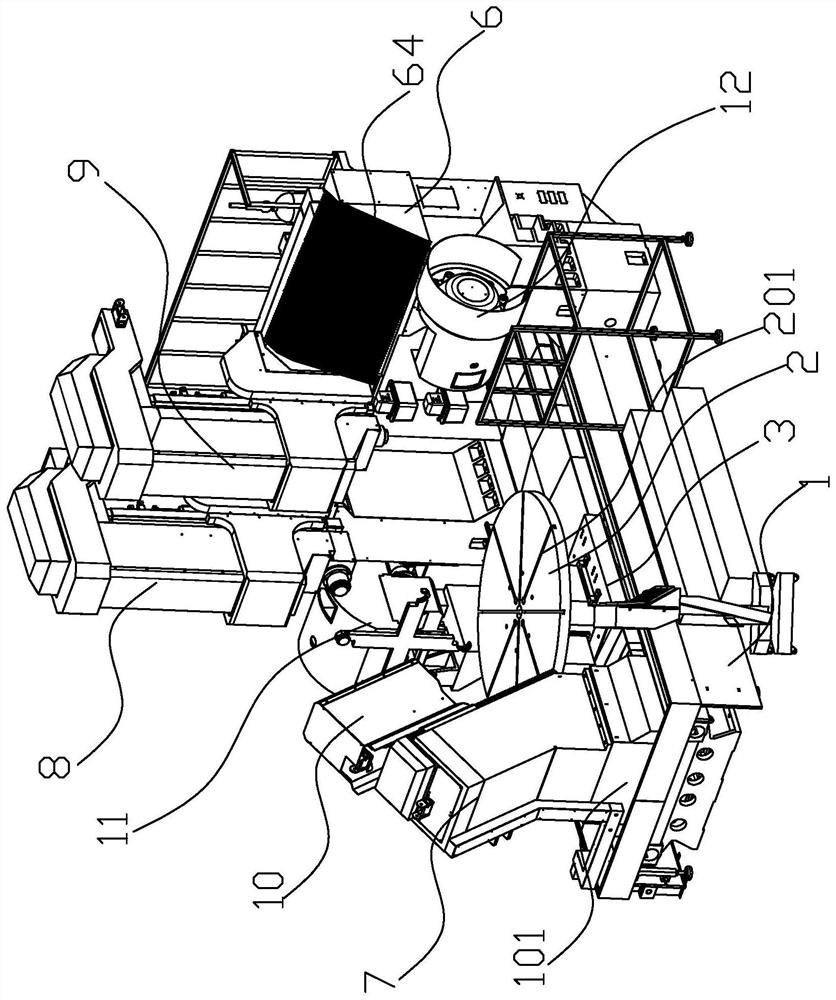
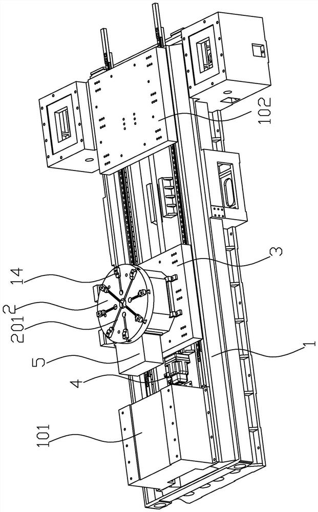
[0022] refer to Figure 2-Figure 7, the preferred CNC gantry compound machine of the present invention includes a frame 1, a workbench 2, a fixed seat 3, a horizontal movement mechanism 4, a drive unit 5, a gantry frame 6, an inclined column 7, a horizontal headstock 8, a first vertical Type spindle box 9, the second vertical spindle box 10, the horizontal tool magazine 11, the first vertical tool magazine 12, the second vertical tool magazine 13 and the clamping mechanism 14, the fixed seat 3 is moved through the horizontal movement mechanism 4 It can be horizontally moved on the frame 1, and the workbench 2 is a circular workbench, and the upper surface of the workbench 2 is uniformly provided with a plurality of card slots extending from the edge to the center of the workbench 2 201, the clamping mechanism 14 includes a plurality of blocks adapte...


PUM


Abstract

The invention relates to a numerically-controlled machine tool, and provides a compound numerically-controlled gantry machine. The compound numerically-controlled gantry machine comprises a rack, a workbench, a fixing base, a horizontal moving mechanism, a driving unit, a gantry frame, an oblique stand column, a horizontal spindle box, a first vertical spindle box, a second vertical spindle box, ahorizontal tool changer, a first vertical tool changer and a second vertical tool changer, wherein both the horizontal spindle box and the first vertical spindle box are slidingly arranged on a beamof the gantry frame, an outer circumferential side and an inner ring inner circumferential side of a to-be-machined circular knitting machine saddle on the workbench are machined by the horizontal spindle box, an upper end surface of the to-be-machined circular knitting machine saddle on the workbench is machined by the first vertical spindle box, and the second vertical spindle box which can vertically slide on an oblique surface of the oblique stand column is arranged on the oblique stand column to machine a lower oblique ring surface, at the outer circumferential side, of the to-be-machinedcircular knitting machine saddle on the workbench. By means of the compound numerically-controlled gantry machine, the problems of low machining efficiency and high production costs of circular knitting machine saddle workpieces, with multidimensional and multistation requirements, according to existing compound machining centers are solved.

Description

technical field [0001] The invention relates to a numerically controlled machine tool, in particular to a numerically controlled gantry composite machine. Background technique [0002] With the revitalization and development of the national equipment manufacturing industry, CNC machine tools, as the mainstream product of the machine tool industry, have become the key equipment to realize the modernization of the equipment manufacturing industry. In the plumbing, hardware, auto parts, compressors, mobile phone 3C and other industries, with the improvement of market requirements, the demand for high-efficiency, high-reliability and high-automation CNC machine tools is also increasing. The multi-functional machining center is a highly automated mechanical processing equipment. Its characteristics are: it has a tool magazine, which can complete the automatic tool change work. After the workpiece is clamped once, according to the pre-programmed NC machining program, the machining...

Claims


Application Information

Patent Timeline
IPC IPC(8): B23Q1/01B23Q1/26B23Q1/64B23Q1/70B23Q11/00B23Q11/08B23Q3/155
CPCB23Q1/012B23Q1/017B23Q1/26B23Q1/64B23Q1/70B23Q3/155B23Q11/0032B23Q11/0816
Inventor 王国金张卯
Owner 泉州市创佳自动化设备有限公司
Learn More