Rotary positioning frame for instrument maintenance

A technology of instrumentation and positioning frame, which is applied in the field of rotating positioning frame for instrumentation maintenance, and can solve problems such as the influence of maintenance accuracy, lack of parts fixing devices, and inconvenient use

Inactive Publication Date: 2021-02-05
广州高腾科技有限公司
View PDF0 Cites 2 Cited by
  • Summary
  • Abstract
  • Description
  • Claims
  • Application Information

AI Technical Summary

Problems solved by technology

[0003] In the prior art, a rotating positioning frame is generally used to maintain instruments and meters. The existing rotating positioning frame is generally composed of a workbench that drives the rotating function. However, if there is an uneven ground in actual use, due to the existing The rotary positioning frame lacks a compensation device for the base, so when the existing device is placed on the ground, it is very likely that the entire workbench will be tilted due to the unevenness of the ground, which will easily affect the maintenance accuracy
[0004] The structure of the currently used rotating positioning frame itself is relatively simple. Various tools and disassembled parts need to be stored when repairing instruments and meters. However, the existing devices lack storage devices for these tools and parts. The surface of the workbench becomes very messy and cannot be regularized, which will easily have a great impact on the quality of maintenance
[0005] In actual use, it is often necessary to fix smaller parts or some parts for further maintenance. However, the working surface of the currently used rotating positioning frame is generally a separate plane, which lacks a fixing device for parts during use. , resulting in the need to use an external fixing device to complete the fixing of the parts during use, which is extremely inconvenient to use
[0006] In the maintenance process of instruments and meters, there may be more precise maintenance. At this time, the parts to be repaired are generally small in size and it is difficult to perform more accurate maintenance with the naked eye. At this time, it is necessary to assist external devices to enlarge and maintain them. , but it needs one hand to hold the magnifying device to complete the auxiliary magnification, and in the actual maintenance, it often needs the cooperation of both hands to complete the maintenance, so the practicability is low

Method used


Image

  • Rotary positioning frame for instrument maintenance
  • Rotary positioning frame for instrument maintenance
  • Rotary positioning frame for instrument maintenance

Examples


Embodiment Construction

[0054] The following will clearly and completely describe the technical solutions in the embodiments of the present invention with reference to the accompanying drawings in the embodiments of the present invention. Obviously, the described embodiments are only some, not all, embodiments of the present invention. Based on the embodiments of the present invention, all other embodiments obtained by persons of ordinary skill in the art without making creative efforts belong to the protection scope of the present invention.

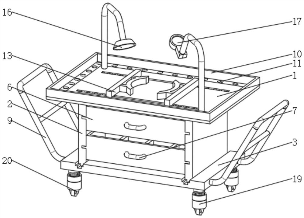
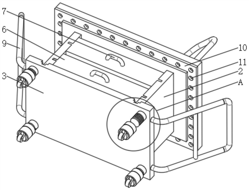
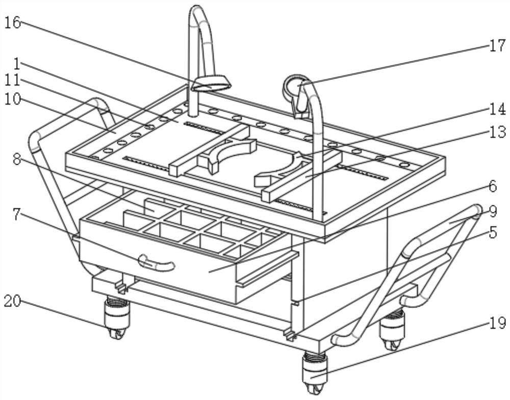
[0055] see Figure 1-5 , a rotary positioning frame for instrumentation maintenance, including a workbench 1, side plates 2 are fixedly installed on the left and right sides of the bottom end of the workbench 1, the bottom end of the side plate 2 is provided with a bottom plate 3, and the four corners of the bottom end of the bottom plate 3 are located All are fixedly installed with threaded column 18, threaded sleeve 19 is connected with threaded sleeve 19 on...


PUM


Abstract

The invention relates to the technical field of instrument maintenance, and discloses a rotary positioning frame for instrument maintenance. The rotary positioning frame comprises a workbench, side plates are fixedly mounted on the left and right sides of the bottom end of the workbench, a bottom plate is arranged at the bottom ends of the side plates, and threaded columns are fixedly mounted at the four corners of the bottom end of the bottom plate. The positions, close to the bottom ends, of the outer side faces of the threaded columns are sleeved with threaded sleeves in a threaded manner.According to the rotary positioning frame for instrument maintenance, the bottom plate is movably installed at the bottom ends of the side plates, the threaded columns are fixed to the four corners ofthe bottom end of the bottom plate, the bottom ends of the threaded columns are sleeved with the threaded sleeves in the threaded manner, when a base needs to be subjected to fine adjustment, the threaded sleeves can be driven by internal threads to move up and down relative to the threaded columns by rotating the threaded sleeves, height compensation is completed by rotating the threaded sleevesto proper positions, meanwhile, moving assemblies at the bottom ends can facilitate movement of the device, and the advantage that auxiliary compensation can be conducted on the height is achieved.

Description

technical field [0001] The invention relates to the technical field of instrumentation maintenance, in particular to a rotating positioning frame for instrumentation maintenance. Background technique [0002] Instrumentation (English: instrumentation) Instrumentation is an appliance or device used to detect, measure, observe, and calculate various physical quantities, material components, and physical parameters. Vacuum leak detectors, pressure gauges, length measuring instruments, microscopes, multipliers, etc. are all instruments. In a broad sense, instruments and meters can also have functions such as automatic control, alarm, signal transmission and data processing, such as pneumatic regulating instruments and electric regulating instruments used in the automatic control of industrial production processes, as well as distributed instrument control systems. instrumentation. Instrumentation improves, extends, or supplements human faculties. People use sensory organs to ...

Claims


Application Information

Patent Timeline
IPC IPC(8): B25H1/06B25H1/12B25H1/10
CPCB25H1/06B25H1/10B25H1/12
Inventor 叶龙威
Owner 广州高腾科技有限公司
Why Eureka
Try Eureka