
Low-power dual-locking lifting track system and method

A double-locking, lifting track technology, applied in lifts, elevators in buildings, transportation and packaging, etc., can solve the problems of cumbersome operation, heavy workload, and complicated track system, and achieve low energy consumption, low cost, and high efficiency. The effect of friction

Active Publication Date: 2021-02-05
NO 63921 UNIT OF PLA
View PDF7 Cites 0 Cited by
  • Summary
  • Abstract
  • Description
  • Claims
  • Application Information

AI Technical Summary

Problems solved by technology

[0009] (1) The track system is complex, and the workload of welding vertical plates and processing holes is large;
[0010] (2) Manually insert the shaft during the lifting process, which is cumbersome to operate and has a large workload;
[0011] (3) Affected by the segmentation of the long holes on the vertical plate, it is impossible to stop and go at any position.

Method used


Image

  • Low-power dual-locking lifting track system and method
  • Low-power dual-locking lifting track system and method
  • Low-power dual-locking lifting track system and method

Examples


Embodiment 1

[0040] see Figure 5 As shown, a low-power double-lock lifting track system includes a low-power double-lock mechanism, and the low-power double-lock mechanism includes a motor device, an trapezoidal screw 106, a screw nut 107 and a lever 109.

[0041] The motor device is fixed on the support 101, and the support 101 can be made of steel plate. The motor 102 device includes a motor 102, a reducer 103 and a shaft coupling 104, and the tail end of the motor 102 has a brake. The motor 102, the reducer 103 and the coupling 104 are connected in sequence. The motor unit is used to provide power.

[0042] The trapezoidal screw 106 is fixedly connected with the motor device, specifically, coaxially fixedly connected with the shaft coupling 104 . The lead screw 106 rotates under the power provided by the motor 102 .

[0043] Lead screw nut 107, it has two, and their thread direction is installed on the lead screw 106 oppositely, under the rotation of lead screw 106, two lead nuts 1...

Embodiment 2

[0051] see Figure 6 As shown, a low-power double-locking lifting track system of this embodiment includes the low-power double-locking lifting track system of Embodiment 1; The upper friction plate 111 is clamped and locked or released.

[0052] Wherein, the extended track 112 can be set on one side of the lifting track mechanism, or can be set on both sides of the lifting track mechanism at the same time.

[0053] The Track 112 is a completely new track design. Compared with the current track system, the vertical plate of the current track system is canceled, and a section of the steel plate of the profile channel steel is elongated, and the elongated part is the track 112 . The rail 112 cooperates with the friction plate 111 for braking.

[0054] Among them, multiple low-power double locking mechanisms can be arranged along the length direction of the track 112 and used simultaneously to increase locking force and safety factor.

[0055] The present invention changes th...


PUM


Abstract

The invention discloses a locking method of a low-power dual-locking lifting track system. The low-power dual-locking lifting track system comprises a motor device which is fixed to a bracket and comprises a motor with a brake, a speed reducer and a coupler which are connected in sequence, a trapezoidal lead screw fixedly connected with the motor device and rotating under the power provided by themotor device, two lead screw nuts installed on the trapezoidal lead screw in opposite thread directions, and moving on the trapezoidal lead screw in opposite directions under the rotation of the trapezoidal lead screw, and two levers. Each lever comprises a power arm, a resistance arm and a fulcrum, each power arm is fixed to the corresponding lead screw nut, and the two fulcrums are fixed to strip-shaped holes of the bracket; and a friction plate is fixed to each resistance arm, and the two lead screw nuts move in the opposite directions to drive the friction plates on the two resistance arms to be clamped, locked or opened. The system is high in automation degree, low in labor intensity and reliable in locking.

Description

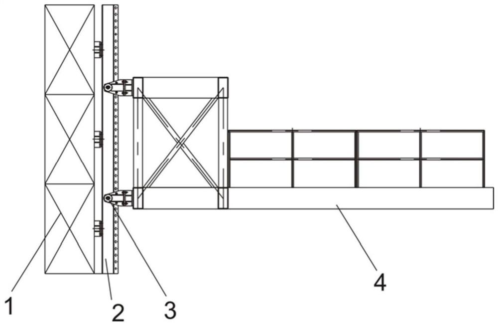
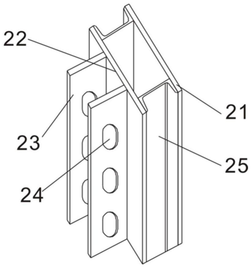
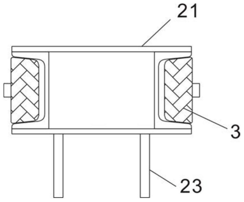
technical field [0001] The invention relates to a low-power double locking lifting track system and method. Background technique [0002] The space launch tower is equipped with a lifting platform system that can be raised and lowered to meet the docking and testing of various subsets of space vehicles such as launch vehicles, satellites, and spacecraft. [0003] see Figure 1-Figure 4 As shown, a current lifting platform system is mainly composed of a track system 2 and a working platform 4. The track system 2 is installed on a fixed foundation 1, and the working platform 4 can be lifted and lowered along the track groove 25 of the track system 2. Specifically, the working platform The platform 4 is fixed with a guide wheel 3, and the working platform 4 runs on the track groove 25 by the guide wheel 3 to guide and lift. [0004] see figure 2 and image 3 As shown, the current track system 2 is mainly composed of a steel plate 21, a profile channel steel 22 and a vertica...

Claims


Application Information

Patent Timeline
Patent Type & Authority Applications(China)
IPC IPC(8): B66B11/04B66B9/02B66B7/02B66B11/02
CPCB66B11/0446B66B9/025B66B7/022B66B11/0293
Inventor 邢伟董强黄科程刚陈强周靖凯王迎东周静涛杨琼
Owner NO 63921 UNIT OF PLA
Learn More