Mounting structure of planet roller and lifting appliance

A technology for installing structures and rolls, which is applied in the direction of rolls, metal rolling, manufacturing tools, etc., can solve the problems of increasing the production cost of copper pipes, difficulties, and the value of rolls cannot be fully utilized, so as to save procurement and production costs and simplify installation Effect

Pending Publication Date: 2021-02-05
海亮奥托铜管(广东)有限公司
View PDF0 Cites 0 Cited by
  • Summary
  • Abstract
  • Description
  • Claims
  • Application Information

AI Technical Summary

Problems solved by technology

This will cause the value of the roll to be underutilized and increase the production cost of the copper pipe
[0004] In order to solve the above problems, the applicant has improved the structure of the planetary roller. For details, please refer to the application number: 2020224491082, the application name: a utility model patent application for an end-face toothed disc type planetary roller, and the application number: 2020224491330 , the name of the application is: a utility model patent application for a convex ring block type planetary roll on the end face. When the roll is lifted, the central axis of the planetary roll will coincide with the central axis of the lifting ring, which changes the installation direction of the planetary roll. Since the assembly position used to realize the installation of the roll shaft and the planetary roll is fixed, if the position of the planetary roll is changed The installation direction will make the installation of the roll shaft and the planetary roll complicated and difficult. Therefore, it is necessary to invent a new type of special hoist for the planetary roll to ensure that when the planetary roll is hoisted, the center axis of the planetary roll and the center of the lifting ring It is necessary to set the axis vertically

Method used


Image

  • Mounting structure of planet roller and lifting appliance
  • Mounting structure of planet roller and lifting appliance
  • Mounting structure of planet roller and lifting appliance

Examples


Embodiment 1

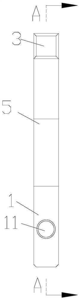
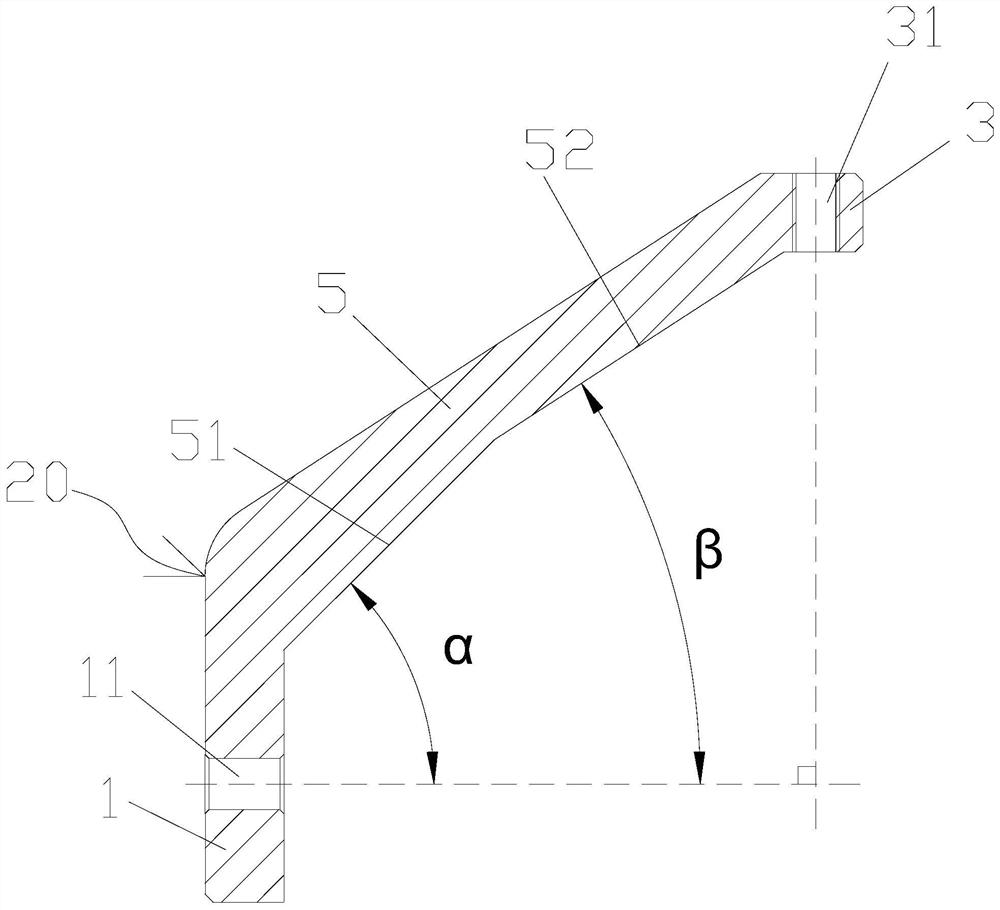
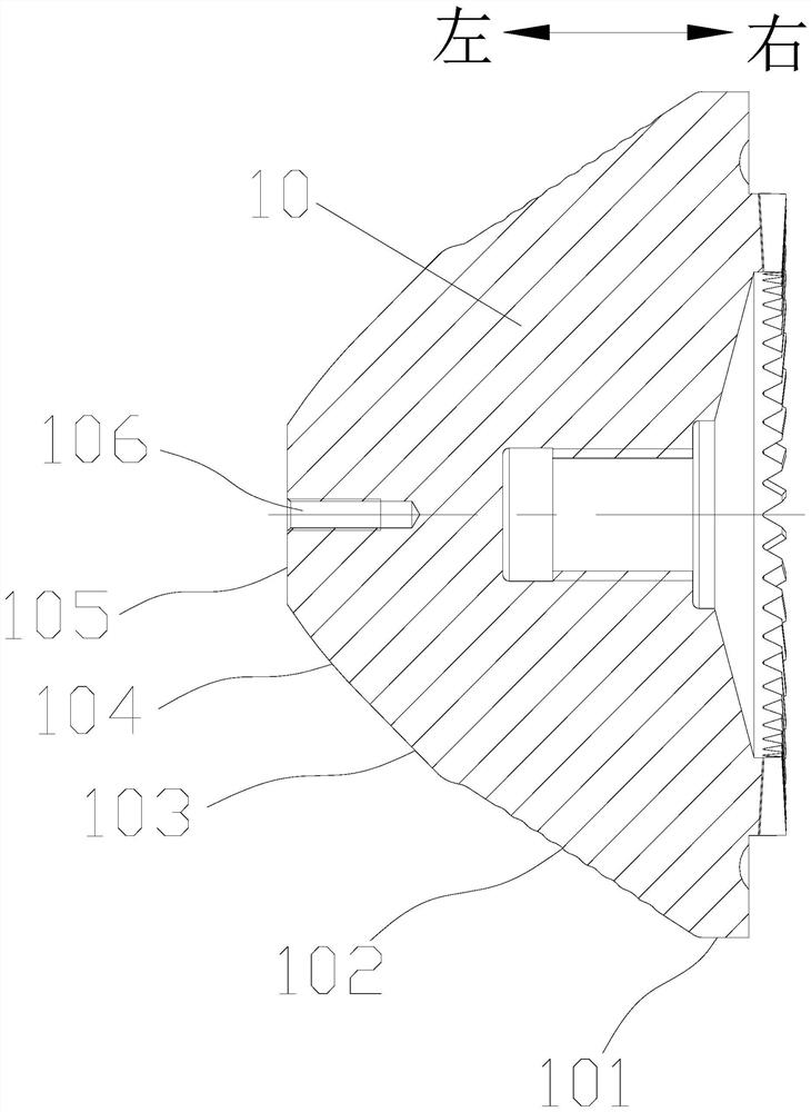
[0032] Such as Figure 1 to Figure 4 As shown, this embodiment provides an installation structure of a planetary roll and a hanger, including a planetary roll 10 and a hanger 20 installed on the planetary roll, the planetary roll 10 is provided with a cylindrical area 101, a bite Entry area 102, diameter reduction and wall reduction area 103, dynamic leveling area 104, and return to circle sizing area 105, on the end face of return to circle sizing area 105, a connection area 106 for connecting with the sling 20 is provided, the sling 20 includes a roll connection part 1, a suspension ring connection part 3 and a connection transition part 5. The roll connection part 1 is provided with a first installation part 11 on the roll connection part 1, and the first installation part 11 is set corresponding to the connection area 106. Through the first The installation part 11 is connected with the connection area 106 to realize the installation of the roll connection part 1 and the p...

Embodiment 2

[0041] Such as Figure 5 to Figure 8 As shown, this embodiment is based on the first embodiment, and the structure of the roll connection part 1 is modified, so that the hanger in this embodiment can be applied to the new type of end-face convex ring block type planetary roll 10, in this embodiment In the embodiment, the cross-sectional shape of the roll connection part 1 is a circle. Since the return-to-circle sizing zone 101 of the end-face convex ring block type planetary roll 10 is provided with an escape hole 1051 corresponding to the connection zone, the circular design Make the contact area between the roll connection part and the end face convex ring block type planetary roll 10 larger, and make the installation of the spreader and the end face convex ring block type planetary roll 10 more stable; the first installation part 11 is a penetrating roll connection part 1 The connecting area 106 of the planetary roll 10 is a screw hole, and the connecting piece 2 is a bolt....

Embodiment 3

[0043] A kind of using method of sling, realizes based on the structure of the sling of embodiment one or embodiment 2, comprises the following steps:

[0044] S1: abut the mounting and positioning surface 51 of the spreader against the contour of the diameter-reducing and wall-reducing area of ​​the planetary roll 10;

[0045] S2: Make the center of the first installation part 11 of the roll connection part 1 correspond to the center of the connection area 106 of the planetary roll 10;

[0046] S3: Thread the connector 2 through the first installation part 11 and screw it to the connection area 106;

[0047] S4: Screw the lifting ring 4 onto the second installation part 31 of the connecting part 3 of the lifting ring;

[0048] S5: pass the sling through the suspension ring 4;

[0049] S6: The hoisting device lifts the planetary roller 10 by retracting the sling, so that the assembly surface of the planetary roller 10 is installed in a vertical state.

[0050] Through the a...


PUM


Abstract

The invention discloses a mounting structure of a planet roller and a lifting appliance. The lifting appliance comprises a roller connecting part, a lifting ring connecting part and a connecting transition part, the roller connecting part is provided with a first mounting part, the planet roller is provided with a connecting area, the first mounting part and the connecting area are correspondinglyarranged, and the first mounting part is connected with the connecting area through a connecting piece to realize mounting of the roller connecting part and the planet roller. The lifting ring connecting part is located above the roller connecting part, a second mounting part is arranged on the lifting ring connecting part, and the second mounting part is used for mounting a lifting ring. The roller connecting part is connected with the lifting ring connecting part through the connecting transition part. The central axis of the first mounting part is perpendicular to the central axis of the second mounting part. By means of the scheme, when the planet roller is lifted, the central axis of the planet roller is perpendicular to the central axis of the lifting ring, it is guaranteed that when the novel planet roller is lifted, the direction cannot be changed, and mounting of the novel planet roller becomes simple and convenient.

Description

technical field [0001] The invention relates to the field of rolling mills, in particular to a mounting structure for a planetary roll and a hanger. Background technique [0002] The three-roll planetary rolling technology in the production of copper pipes for air-conditioning and refrigeration in my country is basically a mature technology commonly used in the industry. Most of the 90-type three-roll planetary rolling mills equipped are used for rolling 90mm series ingots , The three-roll planetary rolling mill has been applied to rolling various pipe fittings. For example, high phosphorus copper tube, oxygen-free copper tube, etc. In the prior art, a three-roll planetary rolling mill generally consists of a fixed frame, a sun gear, a moving rotary pan, three rolls distributed at 120° and loaded into the pan, a gear transmission mechanism, and a central lubrication system. Among them, the roll is generally in the shape of a cone, including a cylindrical area, a bite reduci...

Claims


Application Information

Patent Timeline
Patent Type & Authority Applications(China)
IPC IPC(8): B66C1/62B21B27/02
CPCB21B27/02B66C1/62
Inventor 林锡彬
Owner 海亮奥托铜管(广东)有限公司
Why Eureka
Try Eureka