Plate surface roughness detection device

A surface roughness and detection device technology, which is applied in the direction of measuring devices, instruments, etc., can solve the problems of human deviation of visual inspection method and the inability to accurately characterize the rough effect of interface treatment, so as to avoid human deviation and improve accuracy and precision Effect

Inactive Publication Date: 2021-02-05
合肥潜望镜机械科技有限公司
13 Cites 0 Cited by

AI-Extracted Technical Summary

Problems solved by technology

[0004] The purpose of the present invention is to provide a board surface roughness detection device, which can detect the roughness of building boards, and solv...

Abstract

The invention discloses a plate surface roughness detection device, and relates to the technical field of plate production detection. The device comprises a supporting piece used for fixing a to-be-detected plate, a support assembly used for installing the supporting piece and a resistance sliding block capable of sliding along the surface of the to-be-detected plate. The supporting piece comprises a supporting plate of a rectangular plate-shaped structure, a fixing block is arranged at the top of the supporting plate, two guide rods are movably arranged on the fixing block in a penetrating mode, the two ends of each guide rod are connected with end plates respectively, and locking bolts B matched with the guide rods are arranged on the fixing block; a clamping assembly used for clamping the resistance sliding block is further arranged on the two guide rods in a matched mode. By detecting the sliding distances of the resistance sliding block on the surface of the to-be-detected plate at different inclination angles, the surface roughness of the to-be-detected plate is detected and calculated, and the problem that the interface treatment roughness effect cannot be precisely represented due to human deviation existing in a visual inspection method is avoided; and meanwhile, the roughness detection accuracy and precision are improved.

Application Domain

Technology Topic

Image

  • Plate surface roughness detection device
  • Plate surface roughness detection device
  • Plate surface roughness detection device

Examples

  • Experimental program(1)

Example Embodiment

[0029]The technical solutions in the embodiments of the present invention will be clearly and completely described below in conjunction with the accompanying drawings in the embodiments of the present invention. Obviously, the described embodiments are only a part of the embodiments of the present invention, rather than all the embodiments. Based on the embodiments of the present invention, all other embodiments obtained by those of ordinary skill in the art without creative work shall fall within the protection scope of the present invention.
[0030]In the description of the present invention, it should be understood that the terms "opening", "upper", "lower", "thickness", "top", "middle", "length", "inner", "around", etc. The indication of the orientation or position relationship is only for the convenience of describing the present invention and simplifying the description, rather than indicating or implying that the component or element referred to must have a specific orientation, be constructed and operated in a specific orientation, and therefore cannot be understood as a limitation of the present invention .
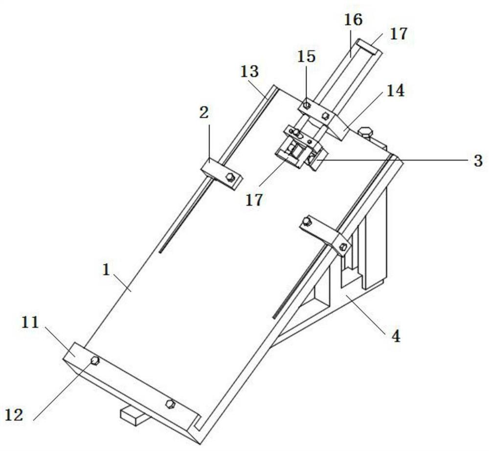
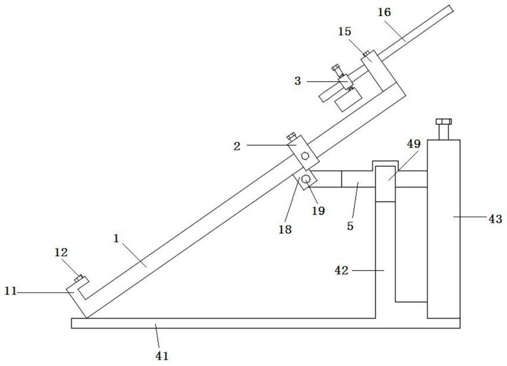
[0031]SeeFigure 1-9As shown, the present invention is a plate surface roughness detection device, including a support for fixing the plate to be tested, a bracket assembly 4 for installing the support, and a resistance slider that can slide along the surface of the plate to be tested; support; The parts include a support plate 1 with a rectangular plate structure. The bottom end of the support plate 1 is provided with an L-shaped flange 11, and a number of locking bolts A12 are provided on the L-shaped flange 11; The locking assembly 2 is used to fix the plate to be tested; the top of the support plate 1 is provided with a fixed block 14, and the fixed block 14 is movably provided with two guide rods 16 therethrough. The two ends of the two guide rods 16 are respectively connected with end plates 17, The fixing block 14 is provided with a locking bolt B15 that cooperates with the guide rod 16; the two guide rods 16 are also provided with a clamping assembly 3 for clamping the resistance slider.
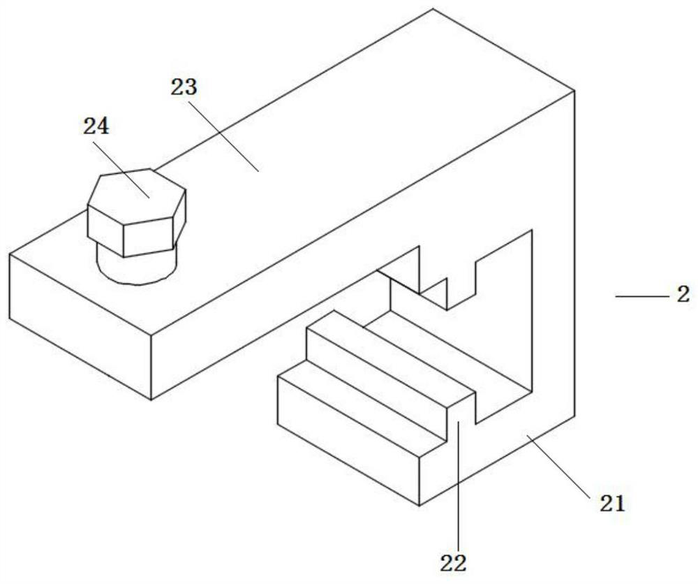
[0032]Preferably, the locking assembly 2 includes a U-shaped card seat 21, and both inner walls of the U-shaped card seat 21 are provided with a guide slide 22, and the upper and lower surfaces of the support plate 1 are provided with slides that cooperate with the guide slide 22. Slot 13; one side of the U-shaped holder 21 is provided with a horizontal plate 23, and the end of the horizontal plate 23 is provided with a locking bolt C24.
[0033]Preferably, the clamping assembly 3 includes a movable block 31 that can move freely along the two guide rods 16. Both ends of the movable block 31 are respectively provided with through holes 32 that are movably penetrated and matched with the guide rods 16, and are used to fix the movable block 31. The locking bolt D33;
[0034]An adjusting screw A34 is arranged in the vertical direction at the center of the movable block 31, the adjusting screw A34 penetrates the movable block 31, and the end is movably connected with a movable plate 35;
[0035]Both ends of the movable plate 35 are provided with a side plate 37, the inner side wall of the side plate 37 is provided with a micro telescopic motor 38, and the end of the micro telescopic motor 38 is provided with a clamping plate 39.
[0036]Preferably, two guiding telescopic members 36 are also connected between the movable plate 35 and the movable block 31. The two guiding telescopic members 36 are respectively located on both sides of the adjusting screw A34 and arranged symmetrically along the adjusting screw A34; the guiding telescopic members 36 include mutually sleeved A spring is connected between the inner sleeve rod and the outer sleeve, and the inner sleeve rod and the outer sleeve.
[0037]Preferably, the bracket assembly 4 includes a bottom plate 41, one end of the bottom plate 41 is hinged to the bottom end of the support plate 1, the other end of the bottom plate 41 is provided with a pillar A42 and a pillar B43; the top of the pillar A42 is provided with a U-shaped hinge seat 49, U-shaped A Y-shaped connecting rod assembly 5 is hinged on the hinge base 49, and one end of the connecting rod assembly 5 is hinged on the lower surface of the support plate 1.
[0038]Preferably, the connecting rod assembly 5 includes a U-shaped frame 51, the outer side of the U-shaped frame 51 is connected with a connecting rod 53, the middle of the connecting rod 53 is provided with a hinge hole A54 hinged with the U-shaped hinge seat 49, and the U-shaped frame 51 A hinge hole B52 is provided on both sides of the opening;
[0039]The lower surface of the support plate 1 is provided with two mounting blocks 18, and a hinge shaft 19 is arranged between the two mounting blocks 18 to be hinged and matched with the hinge hole B52.
[0040]Preferably, the pillar B43 is provided with a rectangular through hole 44 along its length, and two opposite inner side walls of the rectangular through hole 44 are provided with a rectangular slot 45;
[0041]The top of the pillar B43 is provided with an adjusting screw B46. The end of the adjusting screw B46 is movably connected with a sliding block 47 that can move up and down along the length of the rectangular through hole 44. The bottom end of the sliding block 47 is provided with a rectangular opening 473, and the rectangular opening A fixing ring 48 is fitted in the 473; the end of the connecting rod 53 is provided with a fixing column movably connected to the fixing ring 48, and the fixing column penetrates the rectangular through hole 44.
[0042]Preferably, the top of the sliding block 47 is provided with a bearing groove 471, and a bearing 472 is provided in the bearing groove 471, and the end of the adjusting screw B46 is fixedly connected with the inner ring of the bearing 472.
[0043]Preferably, rotating posts 481 are provided on both sides of the fixing ring 48, and two side walls of the rectangular opening 473 are provided with rotating blind holes 474 that cooperate with the rotating posts 481.
[0044]Preferably, the outer peripheral side of one of the guide rods 16 is provided with a graduation line along its length direction, the resistance slider includes a plastic block, a rubber block, a wooden block, a metal block or a ceramic block, and one side of the resistance slider is provided with a rough surface.
[0045]Specifically include:
[0046]Stp1. Put the plate to be tested on the surface of the support plate 1 of the rectangular plate structure of the support. The bottom end of the plate to be tested is pressed into the L-shaped flange 11, and the locking bolt A12 is turned to lock and pass through the edge Move the locking assembly 2 in the longitudinal direction of the chute 13 and rotate the locking bolt C24 at the end of the locking assembly 2 to perform secondary locking;
[0047]Stp2. Control the guide rod 16 to move along the fixed block 14 along the length of the guide rod 16, and lock it by the locking bolt B15 so that the end of the guide rod 16 is located directly above the plate to be tested; control the clamping assembly 3 along the guide rod 16 Move in the length direction and lock it by locking bolt D33;
[0048]Stp3, control the adjustment screw A34 to rotate and extend, so that the bottom side of the movable plate 35 abuts against the surface of the plate to be tested;
[0049]Stp4. Rotate the adjusting screw B46 to control the sliding block 47 to move vertically along the length of the pillar B43, thereby driving the connecting rod assembly 5 to rotate along the U-shaped hinge seat 49 through the action of the fixed ring 48, and passing the connecting rod assembly 5 The rotation of, drives the support plate 1 to turn over as a whole, so that the inclination of the surface of the support plate 1 changes;
[0050]Stp5, adjust the inclination angle to a, put the resistance slider between the clamping plates 39 of the clamping assembly 3 for clamping, and control the miniature telescopic motor 38 to retract. At this time, the resistance slider is released from the clamping assembly 3 and the resistance slide The block slides along the surface of the board to be tested, the sliding distance La is recorded, and the surface roughness of the detected board at this time can be obtained through the formula/standard comparison table as μa;
[0051]Stp6. Adjust the inclination angles to b, c, d and e respectively, and repeat the above Stp5 to obtain the surface roughness μb, μc, μd and μe. Calculate the average value of μa, μb, μc, μd and μe to detect the surface of the sheet Roughness μ0.
[0052]Formula/standard comparison table generation;
[0053]Select 10 plates with surface roughness u1, u2, u3, u4, u5, u6, u7, u8, u9, u10 for the experiment, and just pass the above Stp1-Stp6 operation;
[0054]Among them, the ratio of u1, u2, u3, u4, u5, u6, u7, u8, u9, and u10 is 1:1.5:2:3:4.5:7:10:15:20:50 in order.
[0055]In the description of this specification, the description with reference to the terms "one embodiment", "example", "specific example", etc. means that the specific feature, structure, material or characteristic described in combination with the embodiment or example is included in at least the present invention. In one embodiment or example. In this specification, the schematic representations of the aforementioned terms do not necessarily refer to the same embodiment or example. Moreover, the described specific features, structures, materials or characteristics may be combined in any one or more embodiments or examples in a suitable manner.
[0056]The preferred embodiments of the present invention disclosed above are only used to help explain the present invention. The preferred embodiment does not describe all the details in detail, nor does it limit the invention to only the described specific embodiments. Obviously, many modifications and changes can be made according to the content of this manual. This specification selects and specifically describes these embodiments in order to better explain the principles and practical applications of the present invention, so that those skilled in the art can understand and use the present invention well. The present invention is only limited by the claims and their full scope and equivalents.

PUM

no PUM

Description & Claims & Application Information

We can also present the details of the Description, Claims and Application information to help users get a comprehensive understanding of the technical details of the patent, such as background art, summary of invention, brief description of drawings, description of embodiments, and other original content. On the other hand, users can also determine the specific scope of protection of the technology through the list of claims; as well as understand the changes in the life cycle of the technology with the presentation of the patent timeline. Login to view more.

Similar technology patents

Pretreatment kit for salbutamol sample based on immunomagnetic beads

PendingCN108508199AReduce interference from background substancesImprove accuracy and precisionMaterial analysisChemistryImmunomagnetic bead
Owner:沭阳康源泰博生物科技有限公司

Classification and recommendation of technical efficacy words

Why Eureka
Try Eureka