Quasi-steady-state energy flow analysis method of electricity-water comprehensive energy system

A technology of integrated energy system and analysis method, which is applied in the field of quasi-steady-state energy flow analysis of electricity-water integrated energy system, and can solve problems such as difficult description and slow change of water flow

Active Publication Date: 2021-02-05
CHONGQING UNIV
View PDF11 Cites 0 Cited by
  • Summary
  • Abstract
  • Description
  • Claims
  • Application Information

AI Technical Summary

Problems solved by technology

[0004] However, the existing research on power-water integrated energy systems is based on the steady-state analysis of the power system and water transmission and distribution system. It is believed that the water flow in the pipeline changes very slowly, so the hydraulic state of a point will not change with time. The time scale of the research is mostly on the hour scale
The above models are difficult to describe and analyze the impact of the transient process of the hydraulic system with a time scale of minutes or seconds on the power-hydraulic integrated energy system

Method used


Image

  • Quasi-steady-state energy flow analysis method of electricity-water comprehensive energy system
  • Quasi-steady-state energy flow analysis method of electricity-water comprehensive energy system
  • Quasi-steady-state energy flow analysis method of electricity-water comprehensive energy system

Examples


Embodiment 1

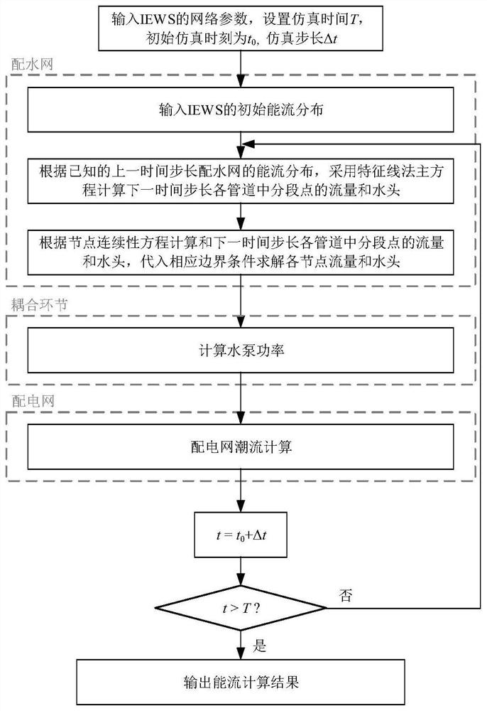
[0083] see Figure 1 to Figure 11 , a quasi-steady-state energy flow analysis method for an electricity-water integrated energy system, comprising the following steps:

[0084] 1) Obtain the network structure parameters of the Electric-Water Integrated Energy System (IEWS), and set the pipeline branch segment points as I, the pipeline segment step size Δx, the time step size as Δt, and the simulation time as T. The segment nodes include upstream and downstream end nodes.

[0085] The pipeline segmentation step size Δx and the time step size Δt satisfy the following relationship:

[0086]

[0087] In the formula, c is the wave velocity of water hammer.

[0088] 2) Obtain the initial steady-state energy flow of the electricity-water integrated energy system, that is, the energy flow distribution of the water distribution network and the power flow distribution of the distribution network at time t=0.

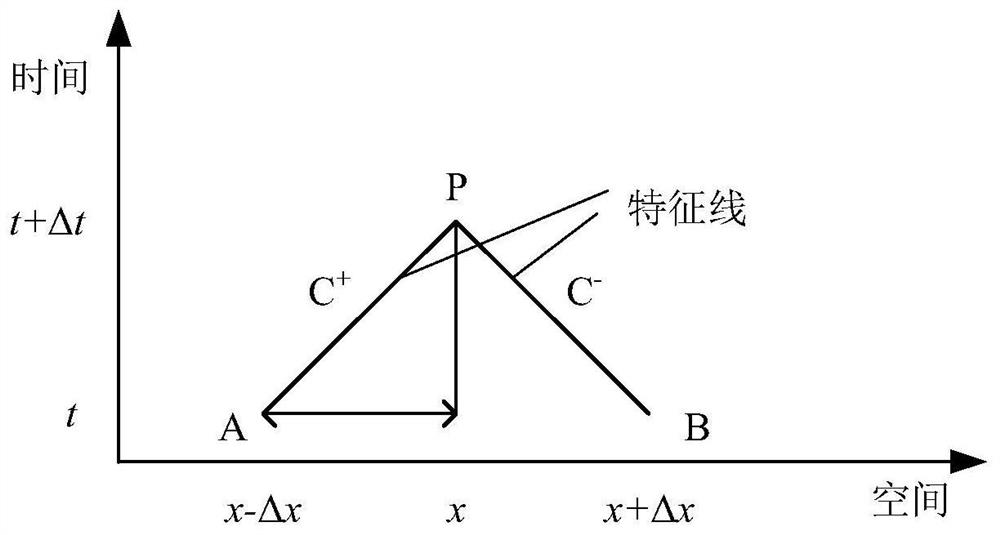
[0089] 3) Using the characteristic line method to calculate the transie...

Embodiment 2

[0149] An IEWS quasi-steady-state energy flow analysis method considering the transient characteristics of the water transmission and distribution system, the steps are as follows:

[0150] 1) Input the network structure parameters of IEWS, set the pipeline branch segment points to 3 (including the upstream and downstream end nodes), the water hammer wave velocity to 1000m / s, the pipeline segment step to 1000m, and the simulation time step to 1s. The simulation time is 120s.

[0151] In order to ensure the accuracy of the solution, Δt and Δx must satisfy the following Courant condition time-space step relationship:

[0152]

[0153] 2) Input the energy flow distribution of the water distribution network and the power flow distribution of the distribution network when t=0.

[0154] 3) Based on the known energy flow distribution of the water distribution network in the previous period, the transient energy flow of the water distribution network in the next simulation step is...

Embodiment 3

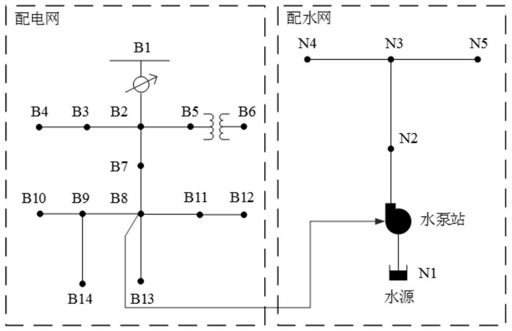
[0203] See attached image 3 , using a test IEWS composed of IEEE-13 distribution network and improved 5-node water distribution network to illustrate the effectiveness of the method proposed in Example 1, the steps are as follows:

[0204] 1) Obtain distribution network data: Letters B and N represent the distribution network bus and distribution network nodes respectively, and the water pumps of the distribution network are connected to the distribution network bus B8. The detailed data of the distribution network are shown in Table 1 and Table 2 :

[0205] Table 1 Water distribution network node data

[0206] Node ID node type Elevation (m) Water load (m 3 / s)

N1 (water source) source of water 0 - N2 end node 0 0 N3 end node 5 0.22 N4 end node 5 0.22 N5 end node 5 0.22

[0207] Table 2 Branch data of water distribution network

[0208]

[0209] 2) Experiment:

[0210] to attach image 3 The test IEWS c...


PUM


Abstract

The invention discloses a quasi-steady-state energy flow analysis method of an electricity-water comprehensive energy system. The method comprises the steps: 1) acquiring network structure parametersof the electricity-water comprehensive energy system; 2) obtaining the initial steady-state energy flow of the electricity-water comprehensive energy system, i.e., the energy flow distribution of thewater distribution network and the tidal current distribution of the power distribution network when the time t is equal to 0. 3) calculating the transient energy flow and the water pump power of thewater distribution network in the next time period by utilizing a characteristic line method; 4) substituting the water pump power of the next time step length into the power distribution network to serve as an electrical load, and calculating the power distribution network energy flow of the next time step length; 5) storing an energy flow calculation result, if the current time t is less than the total duration T, returning to the step 3), otherwise, outputting the energy flow of the power distribution network. According to the method, the transient characteristics of the water distributionnetwork are comprehensively considered in the process of analyzing the energy flow of the electricity-water comprehensive energy system, and the influence of the transient process of the hydraulic system with the time scale of minute level or second level on the electricity-water comprehensive energy system can be analyzed.

Description

technical field [0001] The invention relates to the technical field of comprehensive energy, in particular to a quasi-steady-state energy flow analysis method for an electricity-water comprehensive energy system. Background technique [0002] The increasingly severe energy and environmental crisis in the world has given birth to the rapid development of new energy systems such as energy Internet and integrated energy system (Integrated Energy System, IES). As the physical carrier of the Energy Internet, the integrated energy system has the basic characteristics of breaking down the industry barriers of various heterogeneous energy systems and realizing the interconnection, mutual aid and comprehensive utilization of various energy sources, and has become an important development direction of the future energy system. [0003] Although the power system and the water transmission and distribution system have been in the mode of independent planning and separate operation for a...

Claims


Application Information

Patent Timeline
Patent Type & Authority Applications(China)
IPC IPC(8): G06F30/20G06Q50/06G06F113/04G06F113/14
CPCG06F30/20G06Q50/06G06F2113/04G06F2113/14
Inventor 赵霞孙名轶王骆谭红李欣怡
Owner CHONGQING UNIV
Why Eureka
Try Eureka