
LED backlight module with large light emitting angle, and display device

A light-emitting angle and backlight module technology, applied in the TV field, can solve the problems of not conforming to the mainstream market design trend of thin and light machines, and the overall thickness of the LED backlight module increases, so as to improve the optical quality, reduce the amount of chips, and improve the cost performance. Effect

Pending Publication Date: 2021-02-05
江西兆驰光元科技股份有限公司
View PDF0 Cites 0 Cited by
  • Summary
  • Abstract
  • Description
  • Claims
  • Application Information

AI Technical Summary

Problems solved by technology

[0003] The purpose of the present invention is to provide an LED backlight module and a backlight module with a large light emitting angle, so as to solve the problem that the light emitting angle of the light source of the existing LED backlight module is generally about 120°, which needs to be used with a lens, and the LED light emitting angle is relatively large. Small, under a specific LED pitch pitch, the light mixing distance needs to be larger to meet the good macro light mixing effect, which means that the overall thickness of the LED backlight module will increase, which does not meet the current mainstream market where the whole machine is light and thin design trends etc.

Method used


Image

  • LED backlight module with large light emitting angle, and display device
  • LED backlight module with large light emitting angle, and display device
  • LED backlight module with large light emitting angle, and display device

Examples


Embodiment Construction

[0017] In order to make the object, technical solution and beneficial effects of the present invention more clear, the present invention will be further described in detail below in conjunction with the accompanying drawings and embodiments. It should be understood that the specific embodiments described here are only used to explain the present invention, not to limit the present invention.

[0018] In order to illustrate the technical solutions of the present invention, specific examples are used below to illustrate.

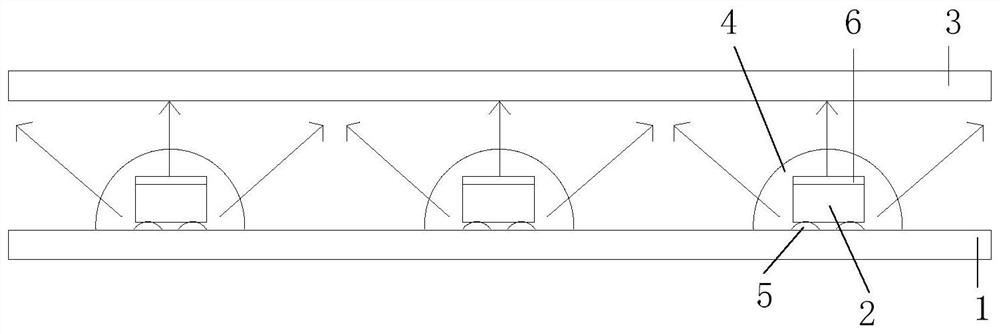
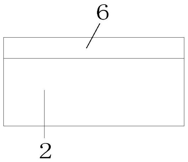
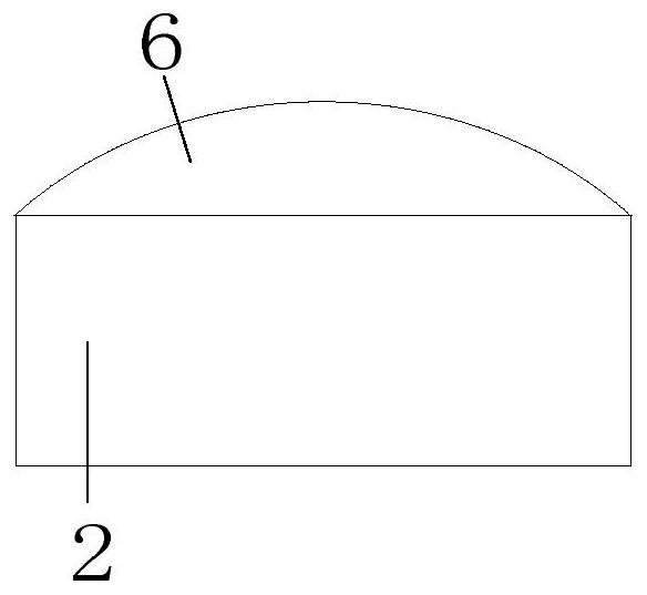
[0019] see Figure 1 to Figure 3 The LED backlight module with a large light output angle provided in Embodiment 1 of the present invention includes a PCB substrate 1, several LED chips 2, a diffusion sheet 3 and an encapsulant 4, and the surface of the PCB substrate 1 is provided with tin points 5, The LED chip 2 is fixed on the tin point 5 by means of solid crystal; the top surface of the LED chip 2 is provided with a reflective layer structure 6 molded by ...


PUM


Abstract

The invention relates to the technical field of televisions, and especially relates to an LED backlight module with a large light emitting angle, and a display device. Tin points are arranged on the surface of a PCB substrate, and an LED chip is fixed on the tin points in a die bonding manner; and the top surface of the LED chip is provided with a reflecting layer structure formed by injection molding through a mold, and the periphery and the upper part of the LED chip are wrapped in packaging colloid in a dispensing manner. The reflecting layer structure on the top surface of the LED chip issubjected to mold injection molding treatment, the periphery and the upper part of the LED chip are wrapped in the packaging colloid in the dispensing manner and are baked and molded, and a diffusionsheet is arranged above the LED chip, so that top light emission is effectively weakened, more light is emitted from the four side surfaces of the LED chip, and the light emission angle of the LED chip is larger. Therefore, according to the LED backlight module with the large light emitting angle, the light emitting angle of the LED chip is increased, and the optical quality is improved; and the use amount of chips is reduced, the cost performance is improved, and the cost is reduced.

Description

technical field [0001] The invention relates to the technical field of televisions, in particular to an LED backlight module and a display device with a large light output angle. Background technique [0002] Most of the existing LED backlight module light sources are used in the field of TV backlight. At present, LED backlight modules usually use LED light sources with bowl-shaped SMD traditional lamp bead light sources. The light output angle is generally around 120°. It needs to be used with a lens to increase the light output angle. , so that a uniform display surface light source can be achieved under a certain LED chip pitch and light mixing distance OD; in addition, the light emitting angle of the LED chip is small, and under a specific LED chip pitch, the light mixing distance needs to be larger to meet good conditions. The micro-distance mixing effect means that the overall thickness of the LED backlight module will increase, which does not meet the current mainstre...

Claims


Application Information

Patent Timeline
IPC IPC(8): H01L25/075H01L33/58H01L33/60
CPCH01L25/0753H01L33/58H01L33/60
Inventor 周波何至年唐其勇朱弼章
Owner 江西兆驰光元科技股份有限公司
Features
  • Generate Ideas
  • Intellectual Property
  • Life Sciences
  • Materials
  • Tech Scout
  • Unparalleled Data Quality
  • Higher Quality Content
  • 60% Fewer Hallucinations
Learn More