Liftable electrical plugboard

A plug-in board and electrical technology, which is applied in the direction of electrical components, circuits, cleaning methods using tools, etc., can solve the problems of large plugs and cannot be plugged into two jacks, so as to achieve convenient connection, avoid electrical safety accidents, The effect of improving the safety factor of electricity use

Inactive Publication Date: 2021-02-05
HUBEI UNIV OF TECH
View PDF1 Cites 2 Cited by
  • Summary
  • Abstract
  • Description
  • Claims
  • Application Information

AI Technical Summary

Problems solved by technology

[0005] Based on the technical problem that the existing socket board may not be plugged into two jacks at the same time due to the large volume of the plug, the present invention proposes a liftable electrical socket board

Method used


Image

  • Liftable electrical plugboard
  • Liftable electrical plugboard
  • Liftable electrical plugboard

Examples


Embodiment 1

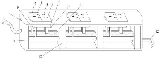
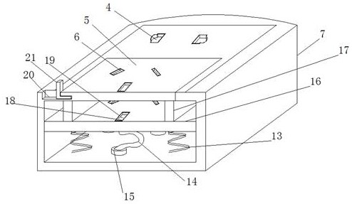
[0030] refer to Figure 1-5 , a liftable electrical plug-in board, comprising a shell 1, a connection bus 2 is welded on one side of the shell 1, a plurality of wiring grooves 7 are welded on the top of the shell 1, and a connecting plate 3 is welded on the top of the wiring groove 7, and the connection The surface of the plate 3 is provided with an arc-shaped opening, and the connecting plate 3 is provided with an L-shaped plate 5 at the arc-shaped opening. The bottom ends of both sides of the L-shaped plate 5 are welded with a slide plate 17, and the bottom end of the slide plate 17 is welded with a clamping plate 16. The top ends of the connecting plate 3 and the L-shaped plate 5 are provided with a first socket 4 and a second socket 6 respectively, and the clamping plate 16 is provided with connection grooves below the first socket 4 and the second socket 6 18. A metal plate 19 is welded inside the connection groove 18, and a first spring 13 is welded between the clamp pla...

Embodiment 2

[0039] refer to Image 6 , a liftable electric board. Compared with Embodiment 1, in order to improve the stability of the board when it is hung on the wall, the inside of the hanging ring 32 is provided with an arc-shaped rubber block 35. The arc-shaped Both sides of the rubber block 35 are welded with triangular rubber strips 33, and the middle part of the arc-shaped rubber block 35 is provided with a circular hole 34. When the interior is deformed, the triangular rubber strip 33 expands, and the triangular rubber strip 33 bends at the same time. The deformation force of the triangular rubber strip 33 prevents the hanging ring from slipping off the wall stud, and improves the stability of the plugboard hanging on the wall. .

[0040] When in use, when the plug of the electrical appliance cannot be inserted on the plug board at the same time, first insert the three-hole plug into the second jack 6, the electrical plug is in contact with the metal plate 19, the internal struc...


PUM


Abstract

The invention belongs to the technical field of electrical equipment, particularly relates to a liftable electrical plugboard, and aims to solve the technical problem that plugs cannot be plugged intotwo jacks at the same time due to the fact that the sizes of the plugs of an existing plugboard are possibly too large, and the liftable electrical plugboard comprises a shell, one side of the shellis fixedly connected with a connecting bus, a plurality of wiring grooves are fixedly connected to the top end of the shell, a connecting plate is fixedly connected to the top ends of the wiring grooves, an arc-shaped opening is formed in the surface of the connecting plate, an L-shaped plate is arranged at the arc-shaped opening of the connecting plate, sliding plates are fixedly connected to thebottom ends of the two sides of the L-shaped plate, and clamping plates are fixedly connected to the bottom ends of the sliding plates. A first inserting hole and a second inserting hole are formed in the top end of the connecting plate and the top end of the L-shaped plate respectively, and connecting grooves are formed in the positions, below the first inserting hole and the second inserting hole, of the clamping plate. According to the invention, through the arrangement of the L-shaped plate, after the plug is inserted into the plugboard, the plug and the connecting piece thereof are integrally lifted, so that the utilization space of the surface of the plugboard is improved, and convenience is brought.

Description

technical field [0001] The invention relates to the technical field of electrical equipment, in particular to a liftable electrical socket. Background technique [0002] In our daily life, we often use a variety of electrical appliances. When these electrical appliances are in use, they need to be plugged into the plugboard. Each plugboard is mostly divided into three-hole sockets and two-hole sockets according to power. Socket, in order to make the use of electrical appliances safer and more convenient. [0003] After retrieval, the Chinese Patent Publication No. is CN102570213B, which discloses an uninterruptible power detection combination board, a live pluggable detection board and a power supply board. The uninterruptible power detection combination board includes: a power supply board and a chargeable The plug-in detection plug-in board, the power plug-in board includes: a power socket and an uninterruptible power detection socket, and the uninterruptible power detect...

Claims


Application Information

Patent Timeline
Patent Type & Authority Applications(China)
IPC IPC(8): H01R27/02H01R24/00H01R13/73B08B1/00
CPCB08B1/006H01R13/73H01R24/00H01R27/02
Inventor 汪繁荣宋强李渊彭禄
Owner HUBEI UNIV OF TECH
Why Eureka
Try Eureka