Card guide and heatsink assemblies for pluggable electro-optic modules

a technology of electro-optic modules and heatsinks, which is applied in the direction of electrical apparatus casings/cabinets/drawers, coupling device connections, instruments, etc., can solve the problems of increasing the routing complexity of the board, not readily applicable at the circuit pack level, and negatively affecting the availability of the bottom of the board

Inactive Publication Date: 2009-10-08
CIENA
View PDF3 Cites 22 Cited by
  • Summary
  • Abstract
  • Description
  • Claims
  • Application Information

AI Technical Summary

Benefits of technology

[0005]In one exemplary embodiment, the present invention provides a solderable surface-mounted card guide assembly configured to receive and ensure the connectivity of a pluggable electro-optic module into an optical communications component including a board, the solderable surface-mounted card guide assembly including: a plurality of card guides, wherein each of the plurality of card guides includes an internally-slotted rail that is configured to slidingly receive a guide manufactured into a side of the pluggable electro-optic module; one or more tooling pins disposed on a bottom surface of each of the plurality of card guides and configured to selectively engage a corresponding hole manufactured or drilled into the board of the optical communications component; and one or more solderable mounting tabs disposed along a length of each of the plurality of card guides and configured to be selectively soldered to a surface of the board of the optical communications component. Optionally, the plurality of card guides are each injection-molded. Optionally, the plurality of card guides are separately formed. Alternatively, the plurality of card guides are integrally formed, and the plurality of card guides are joined by one of a bottom piece and a top piece. Optionally, the one or more solderable mounting tabs are disposed along one side of the length of each of the plurality of card guides. Alternatively, the one or more solderable mounting tabs are disposed along both sides of the length of each of the plurality of card guides. Preferably, the solderable surface-mounted card guide assembly is operable for permanently and precisely receiving and ensuring the connectivity of the pluggable electro-optic module into the optical communications component comprising the board in X, Y, and Z planes.

Problems solved by technology

These card guide assemblies are not readily applicable at the circuit pack level, where guidance for pluggable electro-optic modules, such as small-form factor pluggable electro-optic modules, is required.
The holes created in the board increase the routing complexity of the board by blocking circuit signal routing channels in the board and negatively impact the availability of the bottom of the board for the placement of components.
The current state-of-the-art is limited in its ability to transfer all of the heat present when the circuit pack is plugged into the electronic shelf of the system, however, because, when multiple pluggable electro-optic modules are plugged into the circuit pack, the heatsinks that are located downstream of the incoming air flow are blocked and starved of air flow from the heatsinks that are located upstream.
This negatively limits the number of pluggable electro-optic modules that can be plugged into the circuit pack.

Method used


Image

  • Card guide and heatsink assemblies for pluggable electro-optic modules
  • Card guide and heatsink assemblies for pluggable electro-optic modules
  • Card guide and heatsink assemblies for pluggable electro-optic modules

Examples


Embodiment Construction

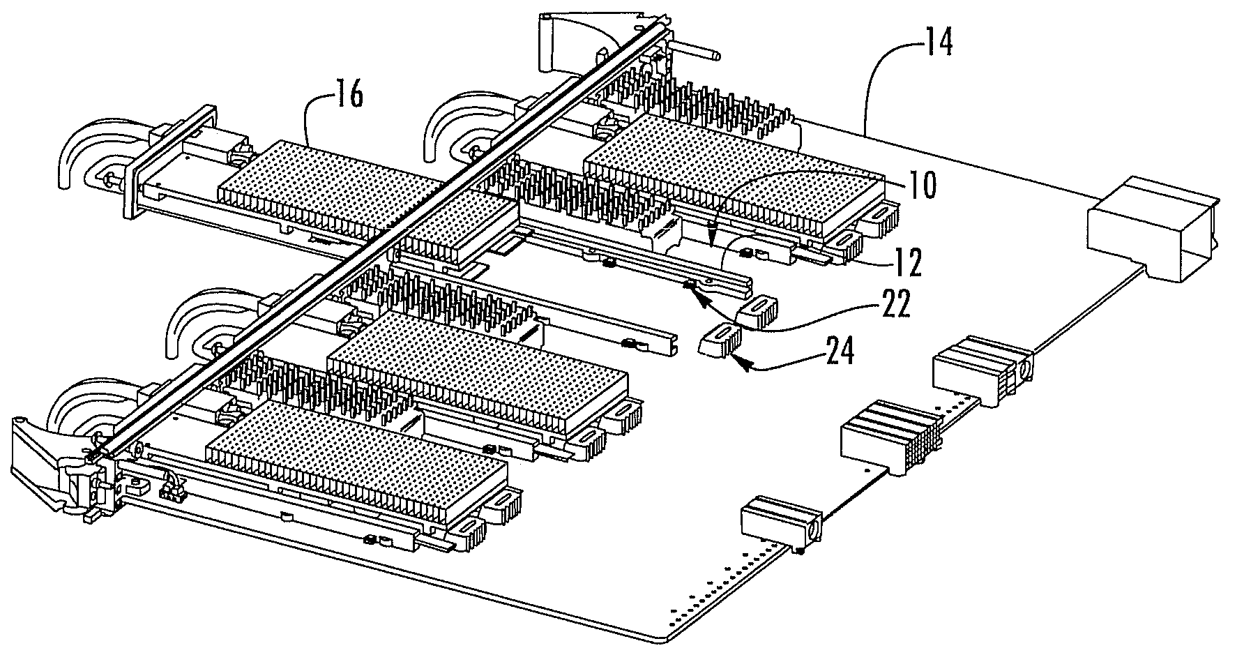
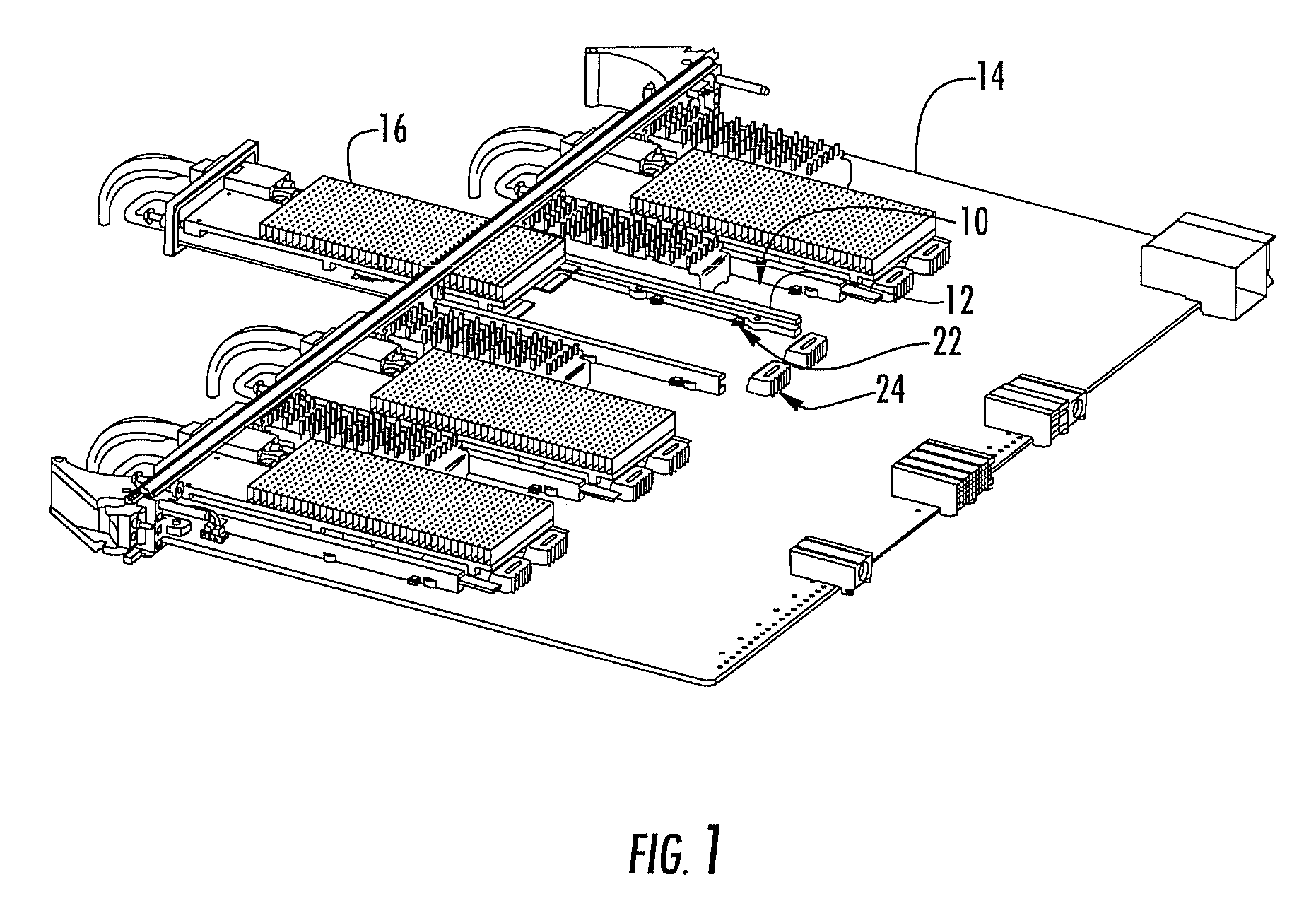
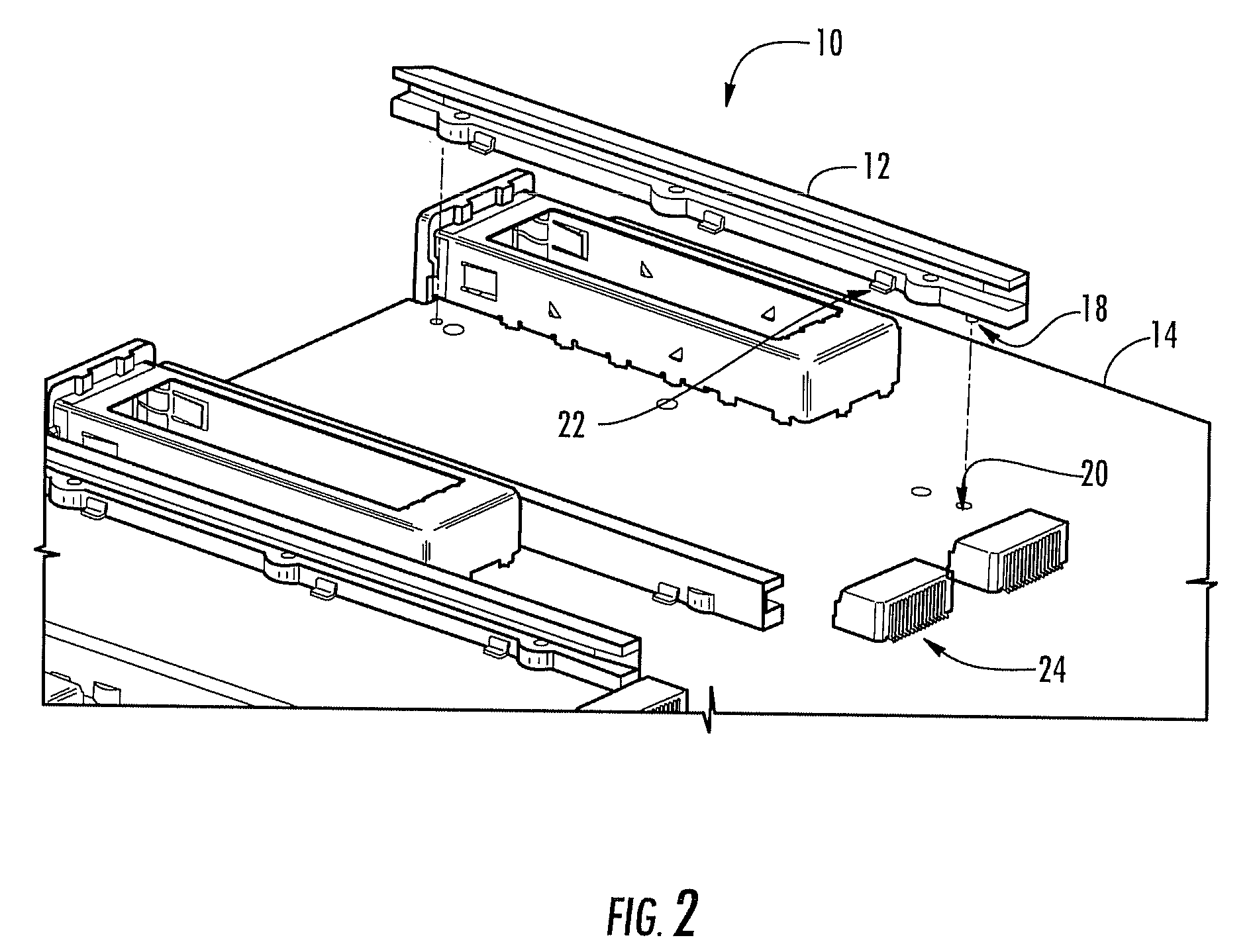
[0015]Referring to FIGS. 1 and 2, the solderable surface-mounted card guide assembly 10 of the present invention includes a plurality of injection-molded card guides 12 that are selectively affixed to the board 14 (such as the PWB) of an optical communications component (not illustrated). The plurality of injection-molded card guides 12 include a plurality of internally-slotted rails or the like that are selectively affixed to the board 14 of the optical communications component such that they are configured to slidingly receive guides (not illustrated) manufactured into either side of a small-form factor pluggable electro-optic module 16 (FIG. 1) or the like. These injection-molded card guides 12 can be separately formed, or they can be integrally formed with an adjoining bottom or top piece (not illustrated), for example. Likewise, as opposed to being injection-molded, the card guides 12 can be formed by any other suitable manufacturing technology, involving plastics, metals, etc....


PUM


Abstract

In various exemplary embodiments, the present invention provides improved card guide and heatsink assemblies for pluggable electro-optic modules utilized in optical communications networks and the like. More specifically, the present invention provides a solderable surface-mounted card guide assembly and a staggered heatsink assembly. These assemblies are utilized with small-form factor pluggable electro-optic modules and the like, and the concepts presented herein can be extended to XFP, XENPAK, XPAK, and X2 electro-optic modules, for example. The solderable surface-mounted card guide assembly of the present invention finds particular applicability with small-form factor pluggable electro-optic modules not utilizing any type of module cage, while the staggered heatsink assembly of the present invention finds particular applicability with small-form factor pluggable electro-optic modules both not utilizing and utilizing any type of module cage.

Description

FIELD OF THE INVENTION[0001]The present invention relates generally to card guide and heatsink assemblies for pluggable electro-optic modules utilized in optical communications networks and the like. More specifically, the present invention relates to a solderable surface-mounted card guide assembly and a staggered heatsink assembly. These assemblies are utilized with small-form factor pluggable electro-optic modules and the like. The solderable surface-mounted card guide assembly finds particular applicability with small-form factor pluggable electro-optic modules not utilizing any type of module cage, while the staggered heatsink assembly finds particular applicability with small-form factor pluggable electro-optic modules both not utilizing and utilizing any type of module cage.BACKGROUND OF THE INVENTION[0002]With respect to optical communications components and the like, conventional card guide assemblies are primarily designed for circuit pack guidance into a shelf or chassis....

Claims


Application Information

Patent Timeline
Patent Type & Authority Applications(United States)
IPC IPC(8): H01R13/64
CPCH05K3/341G02B6/4246G02B6/4266G02B6/4284
Inventor HARRIS, DAVID BENNITT
Owner CIENA
Why Eureka
Try Eureka